
Introductory Circuit Analysis (13th Edition)
13th Edition
ISBN: 9780133923605
Author: Robert L. Boylestad
Publisher: PEARSON
expand_more
expand_more
format_list_bulleted
Related questions
Concept explainers
Question
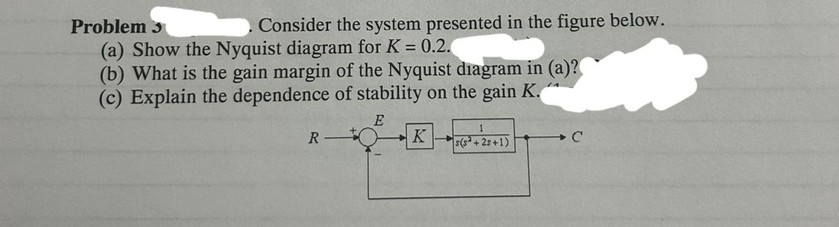

Transcribed Image Text:Problem 3
Consider the system presented in the figure below.
(a) Show the Nyquist diagram for K = 0.2.
(b) What is the gain margin of the Nyquist diagram in (a)?
(c) Explain the dependence of stability on the gain K.
R
E
K
+
1
s(s+25+1)
+C
Expert Solution
This question has been solved!
Explore an expertly crafted, step-by-step solution for a thorough understanding of key concepts.

This is a popular solution

Trending nowThis is a popular solution!

Step by stepSolved in 5 steps with 4 images

Knowledge Booster


Learn more about
Need a deep-dive on the concept behind this application? Look no further. Learn more about this topic, electrical-engineering and related others by exploring similar questions and additional content below.Similar questions
- control system answer step by steparrow_forwardThe filtering stage of a biomedical device passes signals with frequencies ranging between 20 Hz and 500 Hz while the stage delivers a total gain of 48 Design the electronic circuit of the filtering stage using appropriate numbers of operational amplifiers,resistors, and capacitors. (The filtering are all 1st order active filters and the maximum possible gain is limited to 10 for a single amplifier) B. In the circuit, the capacitors are all 318 nF and the feedback-resistors are all 10 k.ohm find the values of the remaining resistors in the circuitarrow_forwardA signal whose energy is concentrated in a frequency band is often referred to as a bandpass signal. There are a variety of techniques for sampling such signals, generally referred to as bandpass-sampling techniques. To examine the possibility of sampling a bandpass signal as a rate less than the total bandwidth, consider the system shown in Figure Q2(b). Assuming that w₁ > W₂ - W₁, find the maximum value of T and the values of the constants A, wa, and wo such that x, (t) = x(t). r x(t) -W₂ -W₁ 1 -Wb X(jw) X +∞ p(t) = Σ 8(t-nT) (a) Xp (t) p(t) 1 W1 W2 H(jw) T H(jw) A- ola @a Wa (b) Wb w 3 x₁ (t)arrow_forward
- Please answer in typing formatarrow_forwardDo c i) and ii)arrow_forwardAs an entry engineer you are assigned the task of designing an averaging circuit of three voltage signals. The signals can come from various sources, like sensors. You decide to design an operational amplifier-based circuit as the one shown below: RE R₁ V10- www R₂ V20 V30 R3 વ્ઝ ટ્રાંસ્ક્રાઇબ કરેલ ટેક્સ્ટ બતાવો C -vo Why would you select an operational amplifier-based circuit? Determine an expression for the output voltage in terms of the input voltages. Determine the relationship between the components of the circuit such that it acts as an averaging system. Select values of components to realize the averaging system.arrow_forward
- Can someone please explain how to solve the problem below?arrow_forwardConsider the integrator circuit shown below. From the input and output graphs shown, determine if this circuit is working correctly, by first determining what the output should be. (Show your working/reasoning.) The output of the integrator shown is given below: Vout Vindt RC The general form of the integral (assuming the input is a cosine) is given by: A A cos(wt)dt = – sin(wt) 100k? 0.2µF 2.2k2 Vout 300 Hz - Output = 3.13 V, PP Input 2.0 V Pp -2 -3 1. 3. 6. 8. 9. 10 Time / [ms] 2. 3. Input/Output Voltage / [V]arrow_forward7) Which of the following is correct for the root locus that starts when the gain value is K-0 ends at K? a) It starts at finite and infinite zeros and ends at finite and infinite poles. b) It must be symmetrical with respect to the imaginary axis. c) The total number of branches is equal to the number of open-loop zeros. d) It must be symmetrical with respect to the real axis. e) It cannot intersect with the real axis.arrow_forward
- LOOP GAIN( NEED ONLY HANDWRITTEN SOLUTION PLEASE OTHERWISE DOWNVOTE).arrow_forward3. In this problem, use the two closed loop systems given in the figure to answer the questions below. 4 R(s) K₁ 0.0099 In thin K₂ Y(s) R(s) K₁ 4 S(s) = 0.09 K₂ 0.09 (a) Show that these two systems have the same transfer function for K₁ = K₂ = 100 (b) Using the definition of sensitivity, S(s), for each system calculate the sensitivity to the parameter K₁ with K₁ and K₂ as variables. Recall: Y(s) OG G OG Gal (c) Substitute K₁ = K₂ = 100 into each S(s) and compare the sensitivities to parameter K₁.arrow_forwardPls do this question correctly and neatly and don't copy from anyone, if I get to know then it won't be good for you pls do on your ownarrow_forward
arrow_back_ios
arrow_forward_ios
Recommended textbooks for you
- Introductory Circuit Analysis (13th Edition)Electrical EngineeringISBN:9780133923605Author:Robert L. BoylestadPublisher:PEARSON
 Delmar's Standard Textbook Of ElectricityElectrical EngineeringISBN:9781337900348Author:Stephen L. HermanPublisher:Cengage Learning
 Programmable Logic ControllersElectrical EngineeringISBN:9780073373843Author:Frank D. PetruzellaPublisher:McGraw-Hill Education
  Fundamentals of Electric CircuitsElectrical EngineeringISBN:9780078028229Author:Charles K Alexander, Matthew SadikuPublisher:McGraw-Hill Education
 Electric Circuits. (11th Edition)Electrical EngineeringISBN:9780134746968Author:James W. Nilsson, Susan RiedelPublisher:PEARSON
 Engineering ElectromagneticsElectrical EngineeringISBN:9780078028151Author:Hayt, William H. (william Hart), Jr, BUCK, John A.Publisher:Mcgraw-hill Education,
Introductory Circuit Analysis (13th Edition)
Electrical Engineering
ISBN:9780133923605
Author:Robert L. Boylestad
Publisher:PEARSON
Delmar's Standard Textbook Of Electricity
Electrical Engineering
ISBN:9781337900348
Author:Stephen L. Herman
Publisher:Cengage Learning
Programmable Logic Controllers
Electrical Engineering
ISBN:9780073373843
Author:Frank D. Petruzella
Publisher:McGraw-Hill Education
Fundamentals of Electric Circuits
Electrical Engineering
ISBN:9780078028229
Author:Charles K Alexander, Matthew Sadiku
Publisher:McGraw-Hill Education
Electric Circuits. (11th Edition)
Electrical Engineering
ISBN:9780134746968
Author:James W. Nilsson, Susan Riedel
Publisher:PEARSON
Engineering Electromagnetics
Electrical Engineering
ISBN:9780078028151
Author:Hayt, William H. (william Hart), Jr, BUCK, John A.
Publisher:Mcgraw-hill Education,