Introductory Circuit Analysis (13th Edition)
13th Edition
ISBN: 9780133923605
Author: Robert L. Boylestad
Publisher: PEARSON
expand_more
expand_more
format_list_bulleted
Question
Thanks

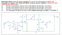
Transcribed Image Text:**Small-Signal Model**
Assume all capacitive reactances, \(X_c\), are very low at the frequency of interest. No calculations are required. **YOU NEED NOT DRAW A SMALL-SIGNAL MODEL!!!!, IDENTIFY THE TOPOLOGIES BY INSPECTION.**
(a) The basic circuit topology of the Q1 circuit is (CE, CB, CC, CS, CG, CD). Circle Choice.
(b) The basic circuit topology of the M1 circuit is (CE, CB, CC, CS, CG, CD). Circle Choice.
(c) The basic circuit topology of the Q2 circuit is (CE, CB, CC, CS, CG, CD). Circle Choice.
(d) The voltage gain of just the Q2 stage is (100, Computed from \(g_{m2}R_7\), Not Quite +1, Not Quite -1).
---
**Circuit Diagram Explanation:**
The diagram shows an electronic circuit with several components including capacitors (C1, C2, C3, C4, C5, C6), resistors (R1, R2, R3, R4, R5, R6, R7, R9), transistors (Q1, Q2), and a MOSFET (M1). It also includes voltage sources (Vin, VDC1, VDC2). The output voltage is labeled as Vout. The topology focuses on different configurations such as common-emitter, common-base, and common-collector for BJTs, and common-source, common-gate, and common-drain for FETs.
Expert Solution
This question has been solved!
Explore an expertly crafted, step-by-step solution for a thorough understanding of key concepts.
Step by stepSolved in 2 steps with 2 images

Knowledge Booster
Learn more about
Need a deep-dive on the concept behind this application? Look no further. Learn more about this topic, electrical-engineering and related others by exploring similar questions and additional content below.Similar questions
- Each unit of a 100-unit hotel is 12 × 15 ft. In addition, there's a 60 × 20 ft officeWhat's the service demand load for conductor sizing for lighting and receptacles?arrow_forward1-Calculate the minimum and maximum protection for an A/C , its conductors(75 ºC) and its grounding. For the following values:1- FLC compressor = 30 A2- FLC condenser = 3 Aarrow_forwardPlease answer in typing formatarrow_forward
- powe calculrionsarrow_forwardAccording to the following specifications, a single solar 295-watt solar panel has maximum power operation voltage at 24 volts. What is the maximum number of solar panels that can be used in a single string? a. 35 solar panels. b. 30 solar panels. c. 25 solar panels. d. 40 solar panels. e. 20 solar panels.arrow_forward
arrow_back_ios
arrow_forward_ios
Recommended textbooks for you
 Introductory Circuit Analysis (13th Edition)Electrical EngineeringISBN:9780133923605Author:Robert L. BoylestadPublisher:PEARSON
 Delmar's Standard Textbook Of ElectricityElectrical EngineeringISBN:9781337900348Author:Stephen L. HermanPublisher:Cengage Learning
 Programmable Logic ControllersElectrical EngineeringISBN:9780073373843Author:Frank D. PetruzellaPublisher:McGraw-Hill Education
 Fundamentals of Electric CircuitsElectrical EngineeringISBN:9780078028229Author:Charles K Alexander, Matthew SadikuPublisher:McGraw-Hill Education
 Electric Circuits. (11th Edition)Electrical EngineeringISBN:9780134746968Author:James W. Nilsson, Susan RiedelPublisher:PEARSON
 Engineering ElectromagneticsElectrical EngineeringISBN:9780078028151Author:Hayt, William H. (william Hart), Jr, BUCK, John A.Publisher:Mcgraw-hill Education,

Introductory Circuit Analysis (13th Edition)
Electrical Engineering
ISBN:9780133923605
Author:Robert L. Boylestad
Publisher:PEARSON

Delmar's Standard Textbook Of Electricity
Electrical Engineering
ISBN:9781337900348
Author:Stephen L. Herman
Publisher:Cengage Learning

Programmable Logic Controllers
Electrical Engineering
ISBN:9780073373843
Author:Frank D. Petruzella
Publisher:McGraw-Hill Education

Fundamentals of Electric Circuits
Electrical Engineering
ISBN:9780078028229
Author:Charles K Alexander, Matthew Sadiku
Publisher:McGraw-Hill Education

Electric Circuits. (11th Edition)
Electrical Engineering
ISBN:9780134746968
Author:James W. Nilsson, Susan Riedel
Publisher:PEARSON

Engineering Electromagnetics
Electrical Engineering
ISBN:9780078028151
Author:Hayt, William H. (william Hart), Jr, BUCK, John A.
Publisher:Mcgraw-hill Education,