
Elements Of Electromagnetics
7th Edition
ISBN: 9780190698614
Author: Sadiku, Matthew N. O.
Publisher: Oxford University Press
expand_more
expand_more
format_list_bulleted
Related questions
Question
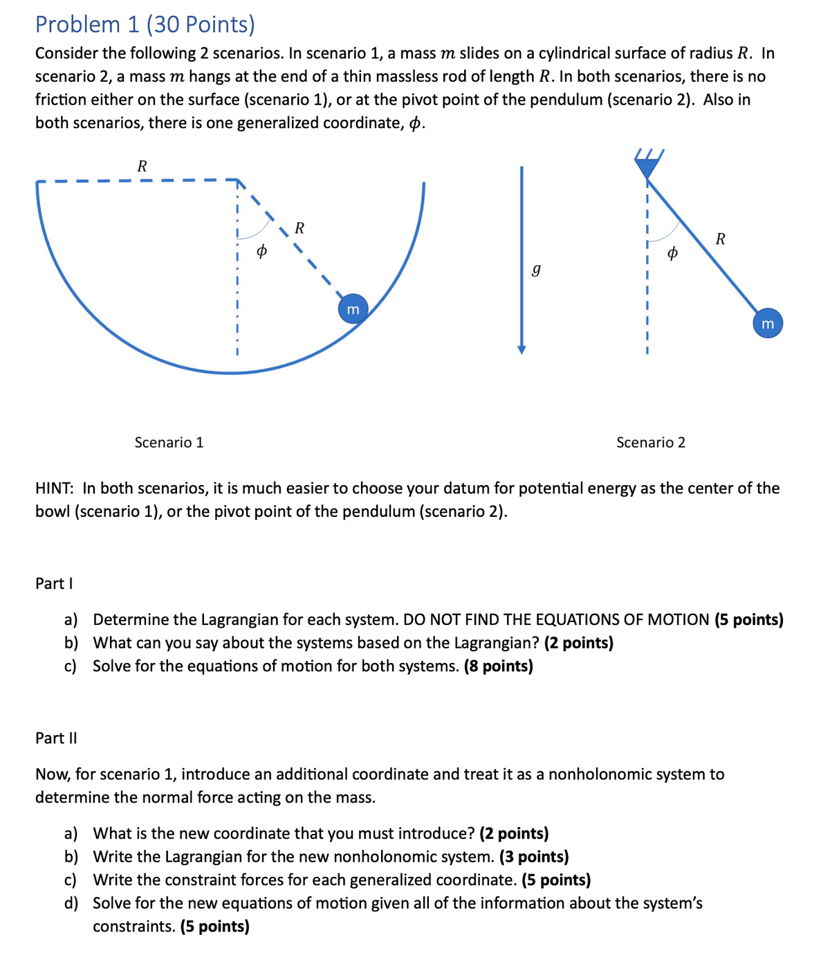

Transcribed Image Text:Problem 1 (30 Points)
Consider the following 2 scenarios. In scenario 1, a mass m slides on a cylindrical surface of radius R. In
scenario 2, a mass m hangs at the end of a thin massless rod of length R. In both scenarios, there is no
friction either on the surface (scenario 1), or at the pivot point of the pendulum (scenario 2). Also in
both scenarios, there is one generalized coordinate, .
R
Scenario 1
R
m
R
g
Scenario 2
m
HINT: In both scenarios, it is much easier to choose your datum for potential energy as the center of the
bowl (scenario 1), or the pivot point of the pendulum (scenario 2).
Part I
a) Determine the Lagrangian for each system. DO NOT FIND THE EQUATIONS OF MOTION (5 points)
b) What can you say about the systems based on the Lagrangian? (2 points)
c) Solve for the equations of motion for both systems. (8 points)
Part II
Now, for scenario 1, introduce an additional coordinate and treat it as a nonholonomic system to
determine the normal force acting on the mass.
a) What is the new coordinate that you must introduce? (2 points)
b) Write the Lagrangian for the new nonholonomic system. (3 points)
c) Write the constraint forces for each generalized coordinate. (5 points)
d) Solve for the new equations of motion given all of the information about the system's
constraints. (5 points)
Expert Solution
This question has been solved!
Explore an expertly crafted, step-by-step solution for a thorough understanding of key concepts.

Step by stepSolved in 2 steps with 5 images

Knowledge Booster

Similar questions
- An object consists of four small spheres attached to the ends of two thin rods that are connected perpendicularly at their centers, forming a cross. Assume each sphere has a mass of m and a radius that is negligible compared to the distance R that each is from the cross’s center (in other words, we can model each as if it were a particle), and that each rod has a mass of m/2. What is a for this object for rotations around an axis perpendicular to the plane of the cross is _____ for rotations around an axis that goes along one of the rods is _____ (Hint: The object’s total mass is not m.)arrow_forwardNeed only a handwritten solution only (not a typed one).arrow_forwardZorch, an archenemy of Superman, decides to slow Earth’s rotation to once per 29 h by exerting a force parallel to the equator, opposing the rotation. Superman is not immediately concerned, because he knows Zorch can only exert a force of 4.15 × 10⁷ N. For the purposes calculations in this problem you should treat the Earth as a sphere of uniform density even though it isn't. a. How long, in seconds, must Zorch push with this force to accomplish his goal? (This period gives Superman time to devote to other villains.)arrow_forward
- Must use equation of motion and please include free body diagram. Thank you!arrow_forwardattached is a past paper question in which we werent given the solution. a solution with clear steps and justification would be massively appreciated thankyou.arrow_forwardHi second question please. This is an engineering statics problem.arrow_forward
- Using equation of motion and please include free body diagram. thank you!arrow_forwardLessons: Static of Rigid Bodies, Force Vector, Addition of a System of Coplanar Forces, Cartesian Vector, Etc. Kindly answer the following with complete solution. Please also draw the free-body diagram or illustration of your figure. Make sure to write with understandable hand-writing. Please send a clear picture of complete solution. I need the answer within an hour at least. I'll rate you with a like/upvote. Thank you.arrow_forwardFor this problem, take a look at Figure 2 below. A disk with uniformly distributed mass m, radius R, and center of mass at point O is connected to a combination of springs at point P, which are then connected to a fixed wall. The disk rolls without slipping at point Q along an inclined plane that is at an angle a from the horizontal. Gravity acts in the vertical direction (towards the bottom of the page). ₁ is the linear coordinate of the point O along the inclined plane. The positive direction of ₁ is as shown. When the springs are undeflected, *₁ = 0. An angle , about the instant center of rotation, is shown. You may assume that the motion (and therefore angle ) is small. puny m Massless structure between springs R Figure 2: System schematic. Your tasks: A Draw the FBD for the disk. Don't forget the forces at point Q B Derive the equation of motion with as the dynamic variable. Be sure to put it in input-output standard form (inputs and constant forces on the right, things related to…arrow_forward
- Lessons: Static of Rigid Bodies, Force Vector, Addition of a System of Coplanar Forces, Cartesian Vector, Etc. Kindly answer the following with complete solution. Please also draw the free-body diagram or illustration of your figure. Make sure to write with understandable hand-writing. Please send a clear picture of complete solution. I need the answer within an hour at least. I'll rate you with a like/upvote. Thank you.arrow_forward3. 3-46. In a motion capture study of a runner, one frame shows the subject support- ing her weight on one leg, as shown in Fig. P3.46. The length of the foot Ankle 30° 60° . Knee x Toes (a) During a motion capture study. Figure P3.46 Position of the runner's leg. segment (from ankle to toe) is 8 in. and the length of the lower leg (from ankle to knee) is 18 in. (a) Given the angles shown in Fig. P3.46(a), find the position of the knee if the runner's toes touch the ground at the point x = y = 0. (b) Now suppose that the same leg is positioned such that the knee is located in the second quadrant and oriented in the knee-down position (clockwise direction), as shown in Fig. P3.46. If the toes are located at P(x, y) = (-6.25 in., 25 in.), de- termine the values of 0₁ and 0₂. (-6.25, 25) Knee 19₂ Ankle y, in. Toes 0₁ (b) To find 0₁ and 0₂. x, in.arrow_forwardneed help with Part D Pleasearrow_forward
arrow_back_ios
SEE MORE QUESTIONS
arrow_forward_ios
Recommended textbooks for you
- Elements Of ElectromagneticsMechanical EngineeringISBN:9780190698614Author:Sadiku, Matthew N. O.Publisher:Oxford University Press
 Mechanics of Materials (10th Edition)Mechanical EngineeringISBN:9780134319650Author:Russell C. HibbelerPublisher:PEARSON
 Thermodynamics: An Engineering ApproachMechanical EngineeringISBN:9781259822674Author:Yunus A. Cengel Dr., Michael A. BolesPublisher:McGraw-Hill Education
  Control Systems EngineeringMechanical EngineeringISBN:9781118170519Author:Norman S. NisePublisher:WILEY
 Mechanics of Materials (MindTap Course List)Mechanical EngineeringISBN:9781337093347Author:Barry J. Goodno, James M. GerePublisher:Cengage Learning
 Engineering Mechanics: StaticsMechanical EngineeringISBN:9781118807330Author:James L. Meriam, L. G. Kraige, J. N. BoltonPublisher:WILEY
Elements Of Electromagnetics
Mechanical Engineering
ISBN:9780190698614
Author:Sadiku, Matthew N. O.
Publisher:Oxford University Press
Mechanics of Materials (10th Edition)
Mechanical Engineering
ISBN:9780134319650
Author:Russell C. Hibbeler
Publisher:PEARSON
Thermodynamics: An Engineering Approach
Mechanical Engineering
ISBN:9781259822674
Author:Yunus A. Cengel Dr., Michael A. Boles
Publisher:McGraw-Hill Education
Control Systems Engineering
Mechanical Engineering
ISBN:9781118170519
Author:Norman S. Nise
Publisher:WILEY
Mechanics of Materials (MindTap Course List)
Mechanical Engineering
ISBN:9781337093347
Author:Barry J. Goodno, James M. Gere
Publisher:Cengage Learning
Engineering Mechanics: Statics
Mechanical Engineering
ISBN:9781118807330
Author:James L. Meriam, L. G. Kraige, J. N. Bolton
Publisher:WILEY