
Elements Of Electromagnetics
7th Edition
ISBN: 9780190698614
Author: Sadiku, Matthew N. O.
Publisher: Oxford University Press
expand_more
expand_more
format_list_bulleted
Related questions
Question
for the values: M1=0.41m, M2=1.8m, M3=0.56m, please account for these in the equations. also please ensure that the final answer is the flow rate in litres per second for each part. please use bernoullis equation where needed if an empirical solutions i srequired. also The solutions should include, but not be limited to, the equations used to
solve the problems, the charts used to solve the problems, detailed working,
choice of variables, the control volume considered, justification and
discussion of results etc.
If determining the friction factor, the use of both Moody chart and empirical
equations should be used to verify the validity of the value

Transcribed Image Text:0.15 m
b
M3
M3
M₂
ДНЕ
DB
0.08 m
M₁
0.15 m
M₂
HE
B
0.08 m
M₁
C
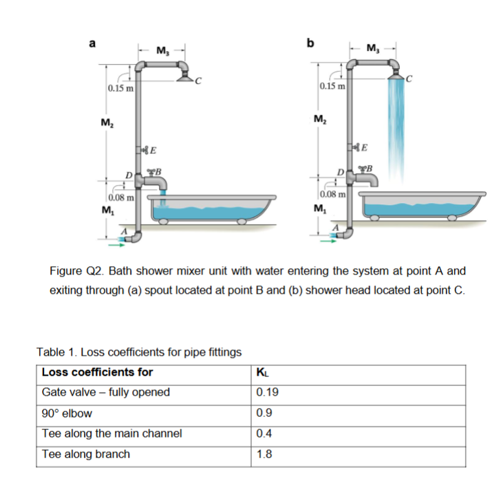
Figure Q2. Bath shower mixer unit with water entering the system at point A and
exiting through (a) spout located at point B and (b) shower head located at point C.
Table 1. Loss coefficients for pipe fittings
Loss coefficients for
KL
Gate valve-fully opened
0.19
90° elbow
0.9
Tee along the main channel
0.4
Tee along branch
1.8

Transcribed Image Text:Part B:
Water at 40 °C (p = 992.3;
kg
and v = 0.664 × 10⁻⁶ m²/s) flows through a pipe at point
A (Figure Q2) with a diameter of 20 mm and a friction factor of f = 0.004. The water
flows into a bath shower mixer unit at D, made from a tee junction. From here, water
can exit along the tee branch through the spout via a gate valve (Figure Q2a) or along
the main channel of the tee and through the showerhead (Figure Q2b). The water
pressure at point A has been measured at 100 kPa. Loss coefficients for pipe fittings
have been provided in Table 1.
(a) If the water exits through the spout (Figure Q2a) via a fully opened gate valve
at B, with a diameter of 12 mm, determine the flow rate out of the spout in L/s.
The minor loss coefficient for the spout at B is Kspout = 0.6. Account for the
minor loss in the elbow, the tee, and the gate valve. The gate valve at E is
closed.
(b) If the water emerges through the showerhead (Figure Q2b, point C) that
consists of 100 identical holes, each with a diameter of 1.5 mm. Determine the
flow rate out of the showerhead in L/s. The minor loss coefficient of the
showerhead is Kshowerhead = 0.45. The gate valve at B is closed. Account for
the minor loss in the three elbows, the fully opened gate valve at E, and the tee.
(c) Discuss the differences in flow rate when water exits through the spout at point
B versus exiting through the showerhead at point C. Justify your answer.
Expert Solution
This question has been solved!
Explore an expertly crafted, step-by-step solution for a thorough understanding of key concepts.

Step by stepSolved in 2 steps with 3 images

Knowledge Booster

Similar questions
- Can You Solve This.arrow_forwardAs shown in the picture blew, a pump can deliver volume flow rate of of water through a vertical lift of . The inlet to the pump is just below the water surface and the discharge is to the atmosphere through a DN50 schedule 40 steel pipe. The energy loss . (2) Select the correct simplified general energy equation for point 1 and 2arrow_forwardB- Calculate the power required for a water pump used in a closed system with flow rate Q=0.0076 m³/s. Assume that section area=0.00511 m² and at the area at the discharge is 0.0037 m². As AJ Water Suction Discharge pump Inlet gauge pressure=147 kPa Outlet gauge pressure=250 kPaarrow_forward
- Inner and outer diameters of an outward flow reaction turbine wheel are 1m and 2m respectively. The water enters the vane at angle of 20° and leaves the vane radially. Assuming the velocity of flow remains constant at 12m/s and wheel rotates at 290rpm, find the vane angles at inlet and outlet. Show schematic diagram and provide solutions.arrow_forward3. A centrifugal pump is to be placed above a large, open water tank, as shown in the figure below. Water is pumped at a rate of I cu ft/s. At this flow rate the required net positive suction head, NPSHR, is 15 ft as specified by the pump manufacturer. The water temperature is 80°F and atmospheric pressure is 14.7 psi. Assume that the major head loss between the tank and the pump inlet is due to filter at the pipe inlet having a minor loss coefficient KL.-20. Other losses can be neglected. The pipe on the suction side of the pump has a diameter of 5 in. The water vapor pressure at 80°F is 0.5069 psia and y-62.22 lb/cu.ft. Determine Z1 for cavitation not to occur.. P1-Patm (1) (2) Reference planearrow_forwardQ1/ liquid is pumped from a ground level reservoir to an overhead tank through a 5 cm ID pipe as shown in Fig. (1): i. What pressure developed by the pump to 45° elbow 8 m Fig. (1) Globe valve Tank 5 m supply water to the tank at the rate of 245 I/min? ii. What is the power required for the pump, if the pump is only 62% efficient? iii. Calculate the available NPSH. If the pump required 12 m NPSH is it suitable to prevent cavitation for this system? why? Given that: u = 0.0016 Pa.s; p 850 kg/m', e/d 0.0035, (Le/d) of Globe valve (open) = 240 (Le/d) of 45° ēlbow = 24 and Pv = 36.6 kPa 25 m 45° Reservoir 45° elbowarrow_forward
- B2arrow_forwardQ3: Size the duct system shown in the figure. The air velocity at the inlet is 8m/s. The length of each duct segment is 4m. If the pressure drop in each diffuser and elbow (or Tee branch) is 20Pa and 25 Pa respectively, calculate pressure head required for the AHU. (Note: CFM=ft³/min.) the AHU 600CFM 800CFM 1000CFM 600CFM 800CFM 1000CFM 600CFM 800CFM 1000CFMarrow_forwardIn Figure below, the pipe entrance is sharp-edged having K1 = 0.5, and for the open globe valve assume K2 = 6.0. The flow rate of water is 0.015 m'/s. 3 (a) Calculate the velocity and Reynolds number of flow. (b) Find the head loss due to friction, hf (in m). (c) Calculate the Turbine head (in m) and Power generated (in Watt). Given: Density of water, pwater = 1000 kg/m²; Viscosity of water, u = 0.001 kg/m.s; Friction factor from Moody Chart, f=0.024. Draw sketch and show all calculations. 1 Open globe valve Turbine 60 m Water Steel pipe: L= 140 m, D = 7.5 cmarrow_forward
- Item#3 The oil tank for the hydraulic system of figure below is air-pressurized at 10psig. The inlet line to the pump is 10 ft below the oil level while point 3 is 2ft below pump inlet. The pump flow-rate is 30 gpm and has a power equal to0.5HP. Find the pressure at station 3if there is a 28ft head loss between station 1 and 3. OIL LEVEL SG 0.9 1.5-IN- INSIDE DIAMETER 10 FT STRAINER ELECTRIC MOTOR M 2 FT PUMP 3 Q-30 GPMarrow_forward3.arrow_forward(b) Figure 3 shows a pump with 80% efficiency (no) delivers 50 Liter/s of water at 20°C from tank 1 to tank 2. The pipeline has 150 mm diameter with a length of 200 m made of galvanised steel. Evaluate the input power to an electric motor of 90% (nm) efficiency that connected to the pump. The globe valve used is % wide open. 2 100 m GLOBE VALVE PRESSURE GAUGE МОTOR PUMParrow_forward
arrow_back_ios
SEE MORE QUESTIONS
arrow_forward_ios
Recommended textbooks for you
- Elements Of ElectromagneticsMechanical EngineeringISBN:9780190698614Author:Sadiku, Matthew N. O.Publisher:Oxford University Press
 Mechanics of Materials (10th Edition)Mechanical EngineeringISBN:9780134319650Author:Russell C. HibbelerPublisher:PEARSON
 Thermodynamics: An Engineering ApproachMechanical EngineeringISBN:9781259822674Author:Yunus A. Cengel Dr., Michael A. BolesPublisher:McGraw-Hill Education
  Control Systems EngineeringMechanical EngineeringISBN:9781118170519Author:Norman S. NisePublisher:WILEY
 Mechanics of Materials (MindTap Course List)Mechanical EngineeringISBN:9781337093347Author:Barry J. Goodno, James M. GerePublisher:Cengage Learning
 Engineering Mechanics: StaticsMechanical EngineeringISBN:9781118807330Author:James L. Meriam, L. G. Kraige, J. N. BoltonPublisher:WILEY
Elements Of Electromagnetics
Mechanical Engineering
ISBN:9780190698614
Author:Sadiku, Matthew N. O.
Publisher:Oxford University Press
Mechanics of Materials (10th Edition)
Mechanical Engineering
ISBN:9780134319650
Author:Russell C. Hibbeler
Publisher:PEARSON
Thermodynamics: An Engineering Approach
Mechanical Engineering
ISBN:9781259822674
Author:Yunus A. Cengel Dr., Michael A. Boles
Publisher:McGraw-Hill Education
Control Systems Engineering
Mechanical Engineering
ISBN:9781118170519
Author:Norman S. Nise
Publisher:WILEY
Mechanics of Materials (MindTap Course List)
Mechanical Engineering
ISBN:9781337093347
Author:Barry J. Goodno, James M. Gere
Publisher:Cengage Learning
Engineering Mechanics: Statics
Mechanical Engineering
ISBN:9781118807330
Author:James L. Meriam, L. G. Kraige, J. N. Bolton
Publisher:WILEY