Introductory Circuit Analysis (13th Edition)
13th Edition
ISBN: 9780133923605
Author: Robert L. Boylestad
Publisher: PEARSON
expand_more
expand_more
format_list_bulleted
Concept explainers
Question

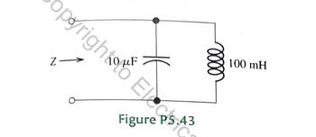
Transcribed Image Text:P5.43. Find the complex impedance of the network
shown in Figure P5.43 for w=500. Repeat
for w= 1000 and w= 2000.

Transcribed Image Text:Z
opyright E
HE
Figure P5.43
0000
100 mH
Expert Solution
This question has been solved!
Explore an expertly crafted, step-by-step solution for a thorough understanding of key concepts.
This is a popular solution
Trending nowThis is a popular solution!
Step by stepSolved in 4 steps with 4 images

Knowledge Booster
Learn more about
Need a deep-dive on the concept behind this application? Look no further. Learn more about this topic, electrical-engineering and related others by exploring similar questions and additional content below.Similar questions
- Find the phasors for the voltage and the currents of the circuit shown in Figure P5.47. Construct a phasor diagram showing Is, V, IR and IL. What is the phase relationship between V and Is ?arrow_forwardP5.26. Write an expression for the sinusoid shown in Figure P5.26 D of the form v(t) = Vm cos(wt + 0), giving the numerical values of V, m, W, and 0. Also, determine the phasor and the rms value of v(t). 2 -1 -2 -3 o 0.1 0.2 0.3 0.4 0.5 0.6 0.7 0.8 0.9 1.0 0.0625 s - 1 (s) Figure P5.26arrow_forwardsee image attached!arrow_forward
- P5.46. Find the phasors for the voltage and the cur- rents of the circuit shown in Figure P5.46. Construct a phasor diagram showing Is, V. IR, and IL. What is the phase relationship between V and Is? 1 H 200 2 0.5 sin(100r) (1)a Figure P5.46arrow_forwardDetermine the initial and final conditions for thecircuit of Figure P5.29.arrow_forwardP5.43. Compute the complex impedance of the net- work shown in Figure P5.43 for w = 500. Repeat for w = 1000 and w = 2000. Give the answers in both polar and rectangular forms. 10 μ 100 mH 100 2 Figure P5.43arrow_forward
- Write the differential equation for t > 0 for thecircuit of Figure P5.52.arrow_forward*P5.21. Suppose that v1(t) = 100 cos(wt) and V2(t) = 100 sin(wt). Use phasors to reduce the sum v, (t) = v1(t) + v2(t) to a single term of the form Vm cos(wt + 0). Draw a phasor diagram, showing V1, V2, and V,. State the phase relationships between each pair of these phasors.arrow_forwardA sinusoidal 100V source (w=100 r/s) has an series resistor and capacitor as shown. This source drives a load, which consist of a parallel combination of a resistor RL and a reactive component (capacitor or inductor) of impedance jXL. Determine the value of RL (load resistor) and XL (load reactive component) that maximizes the power absorbed by the load and the maximum power transferred. + 100 V 100 r/s ww 20 Ω 1.5 mF RL jXLarrow_forward
- P5.45. Find the phasors for the current and the voltages for the circuit shown in Figure P5.45. Construct a phasor diagram showing V₁, I, VR, and Vc. What is the phase relationship between V, and I? S v₂(t) = 10 cos(500r) + + 1000 Ω www VR i Figure P5.45 + VC 2 μF ciples Tarrow_forwardSolve for the mesh currents shown in Figure P5.54.arrow_forwardWrite an expression for the complex impedance of a parallel combination of an inductor, L, and a capacitor, C, as a function of frequency. Find the frequency at which the magnitude of the impedance becomes infinite. What happens to the phase of the impedance at this frequency? What current will the parallel combination draw from an ideal sinusoidal voltage source at this frequency?arrow_forward
arrow_back_ios
SEE MORE QUESTIONS
arrow_forward_ios
Recommended textbooks for you
 Introductory Circuit Analysis (13th Edition)Electrical EngineeringISBN:9780133923605Author:Robert L. BoylestadPublisher:PEARSON
 Delmar's Standard Textbook Of ElectricityElectrical EngineeringISBN:9781337900348Author:Stephen L. HermanPublisher:Cengage Learning
 Programmable Logic ControllersElectrical EngineeringISBN:9780073373843Author:Frank D. PetruzellaPublisher:McGraw-Hill Education
 Fundamentals of Electric CircuitsElectrical EngineeringISBN:9780078028229Author:Charles K Alexander, Matthew SadikuPublisher:McGraw-Hill Education
 Electric Circuits. (11th Edition)Electrical EngineeringISBN:9780134746968Author:James W. Nilsson, Susan RiedelPublisher:PEARSON
 Engineering ElectromagneticsElectrical EngineeringISBN:9780078028151Author:Hayt, William H. (william Hart), Jr, BUCK, John A.Publisher:Mcgraw-hill Education,

Introductory Circuit Analysis (13th Edition)
Electrical Engineering
ISBN:9780133923605
Author:Robert L. Boylestad
Publisher:PEARSON

Delmar's Standard Textbook Of Electricity
Electrical Engineering
ISBN:9781337900348
Author:Stephen L. Herman
Publisher:Cengage Learning

Programmable Logic Controllers
Electrical Engineering
ISBN:9780073373843
Author:Frank D. Petruzella
Publisher:McGraw-Hill Education

Fundamentals of Electric Circuits
Electrical Engineering
ISBN:9780078028229
Author:Charles K Alexander, Matthew Sadiku
Publisher:McGraw-Hill Education

Electric Circuits. (11th Edition)
Electrical Engineering
ISBN:9780134746968
Author:James W. Nilsson, Susan Riedel
Publisher:PEARSON

Engineering Electromagnetics
Electrical Engineering
ISBN:9780078028151
Author:Hayt, William H. (william Hart), Jr, BUCK, John A.
Publisher:Mcgraw-hill Education,