Introductory Circuit Analysis (13th Edition)
13th Edition
ISBN: 9780133923605
Author: Robert L. Boylestad
Publisher: PEARSON
expand_more
expand_more
format_list_bulleted
Concept explainers
Question

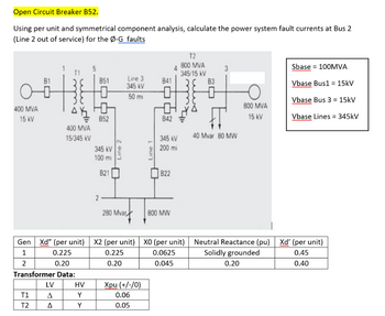
Transcribed Image Text:Open Circuit Breaker B52.
Using per unit and symmetrical component analysis, calculate the power system fault currents at Bus 2
(Line 2 out of service) for the Ø-G faults
400 MVA
15 kV
T1
T2
38
Ah
400 MVA
15/345 kV
LV
Δ
Δ
851
HV
Y
Y
0
Ho
B52
345 kV
100 mi
821
2-
Line 2
Gen Xd" (per unit) X2 (per unit)
1
0.225
0.225
2
0.20
0.20
Transformer Data:
Line 3
345 KV
50 mi
280 Mvard
Xpu (+/-/0)
0.06
0.05
Line 1
841
0
842
345 kV
200 mi
822
800 MW
T2
800 MVA
345/15 kV
XO (per unit)
0.0625
0.045
83
40 Mvar 80 MW
800 MVA
15 kV
Sbase = 100MVA
Vbase Bus1 = 15kV
Vbase Bus 3 = 15kV
Vbase Lines = 345kV
Neutral Reactance (pu) Xd' (per unit)
Solidly grounded
0.45
0.20
0.40
Expert Solution
This question has been solved!
Explore an expertly crafted, step-by-step solution for a thorough understanding of key concepts.
Step by stepSolved in 3 steps with 17 images

Knowledge Booster
Learn more about
Need a deep-dive on the concept behind this application? Look no further. Learn more about this topic, electrical-engineering and related others by exploring similar questions and additional content below.Similar questions
- The subject is: Smart Grid Applications and Technologiesarrow_forwardFigure below shows the single-line diagram of three-bus power system with generation at bus 1 and bus 3. The voltage at bus 1 is V₁ = 1.025/0° per unit. The voltage magnitude at bus 3 is fixed at 1.05 per unit with a real power generation of 250 MW. The scheduled load on bus 2 is marked on the diagram. Line impedances are marked in per unit on a 100 MVA base. Line resistances and line charging susceptances are neglected. By using Gauss-Seidel method and initial estimates of V₂(0) = 1.020° and V3(0) = 1.0520°, determine V₂ and V3. Perform calculation for one iteration. V₁ = 1.025/0° j0.1 Slack Bus j0.2 j0.4 j0.2 3 j0.1 250 MW 150 Mvar |V3|=1.05 P3 = 250 MWarrow_forwardA hydro powered 50 MVA generator, with a synchronous reactance 0.33 p.u., delivers 40 MW over a transmission line of 0.15 p.u. reactance to an infinite system. A 3-phase short circuit transient fault occurs on the busbar between the generator and transmission line. Given that the generator emf is 1.4 p.u. prior to and during the fault and all reactances are to a 50 MVA base: Sketch the single line schematic diagram of the system. Determine the maximum load angle the generator can swing to without losing stability. i) ii) iii) iv) Sketch the corresponding power-angle curve for the system showing the accelerating and decelerating areas. Calculate the critical clearing angle of the system to keep its stability.arrow_forward
Recommended textbooks for you
 Introductory Circuit Analysis (13th Edition)Electrical EngineeringISBN:9780133923605Author:Robert L. BoylestadPublisher:PEARSON
 Delmar's Standard Textbook Of ElectricityElectrical EngineeringISBN:9781337900348Author:Stephen L. HermanPublisher:Cengage Learning
 Programmable Logic ControllersElectrical EngineeringISBN:9780073373843Author:Frank D. PetruzellaPublisher:McGraw-Hill Education
 Fundamentals of Electric CircuitsElectrical EngineeringISBN:9780078028229Author:Charles K Alexander, Matthew SadikuPublisher:McGraw-Hill Education
 Electric Circuits. (11th Edition)Electrical EngineeringISBN:9780134746968Author:James W. Nilsson, Susan RiedelPublisher:PEARSON
 Engineering ElectromagneticsElectrical EngineeringISBN:9780078028151Author:Hayt, William H. (william Hart), Jr, BUCK, John A.Publisher:Mcgraw-hill Education,

Introductory Circuit Analysis (13th Edition)
Electrical Engineering
ISBN:9780133923605
Author:Robert L. Boylestad
Publisher:PEARSON

Delmar's Standard Textbook Of Electricity
Electrical Engineering
ISBN:9781337900348
Author:Stephen L. Herman
Publisher:Cengage Learning

Programmable Logic Controllers
Electrical Engineering
ISBN:9780073373843
Author:Frank D. Petruzella
Publisher:McGraw-Hill Education

Fundamentals of Electric Circuits
Electrical Engineering
ISBN:9780078028229
Author:Charles K Alexander, Matthew Sadiku
Publisher:McGraw-Hill Education

Electric Circuits. (11th Edition)
Electrical Engineering
ISBN:9780134746968
Author:James W. Nilsson, Susan Riedel
Publisher:PEARSON

Engineering Electromagnetics
Electrical Engineering
ISBN:9780078028151
Author:Hayt, William H. (william Hart), Jr, BUCK, John A.
Publisher:Mcgraw-hill Education,