Elements Of Electromagnetics
7th Edition
ISBN: 9780190698614
Author: Sadiku, Matthew N. O.
Publisher: Oxford University Press
expand_more
expand_more
format_list_bulleted
Concept explainers
Question
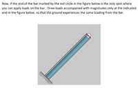
I need help with the "Now, if the end of the bar marked by the red circle in the figure below is the only spot where you can apply loadson the bar. Draw loads accompanied with magnitudes only at the indicated end in the figure below, so that the ground experiences the same loading from the bar. " part

Transcribed Image Text:Now, if the end of the bar marked by the red circle in the figure below is the only spot where
you can apply loads on the bar. Draw loads accompanied with magnitudes only at the indicated
end in the figure below, so that the ground experiences the same loading from the bar.

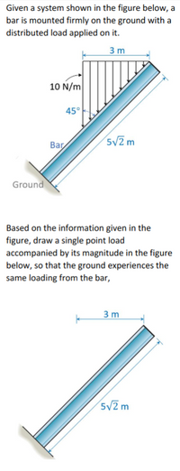
Transcribed Image Text:Given a system shown in the figure below, a
bar is mounted firmly on the ground with a
distributed load applied on it.
3 m
10 N/m
45°
52 m
Bar
Ground
Based on the information given in the
figure, draw a single point load
accompanied by its magnitude in the figure
below, so that the ground experiences the
same loading from the bar,
3 m
5V2 m
Expert Solution
This question has been solved!
Explore an expertly crafted, step-by-step solution for a thorough understanding of key concepts.
This is a popular solution
Trending nowThis is a popular solution!
Step by stepSolved in 2 steps with 1 images

Knowledge Booster
Learn more about
Need a deep-dive on the concept behind this application? Look no further. Learn more about this topic, mechanical-engineering and related others by exploring similar questions and additional content below.Similar questions
- I-section built-in beam in the figure shows two forces It is in effect. These forces at point A and B stress element by finding the stresses that it generates Please show on. Note: force of 100 kN It is in the x-y plane and the point of action is Take as its surface. Force with a magnitude of 180 kN I is in the center of gravity of the section (Search all show transactions and required reductionsarrow_forward2. In the figure below, what is the equivalent force at point O? -200 lb 200 lb 700 Ib -500 Ib Check Answer Input an answer - this line will update depending on your answer. 1.2 ft 500 lb 250 lb – ft 700 lb 2 ftarrow_forwardQ is the midpoint of the line segment PR in the truss rafter shown in the figure. What are the lengths of the line segments PQ, QS, and RS? (Let x = 7 and y = 14. Round your answer to one decimal place.) PQ- 7 QS = 7 RS= Rarrow_forward
- A cross-section of a beam is shown in Figure Q2. If the shear force in this section is V determine the value and the location of the maximum shear stress in the section. In Figure Q2, a = 68 mm and the origin of the coordinate system is at centroid of the cross section. y= A Z= a I₂ = S = AY mm; Figure Q2 Answer The vertical coordinate (y-coordinate; the y-axis serves as the axis of symmetry of the cross- section.) and horizontal coordinate (z-coordinate) of the location where the maximum shear stress occurs in the section are mm; O 4a Tmax= The vertical distance from the location where the maximum shear stress occurs in the section to the bottom side (AB) of the cross section can be calculated as Distance = mm B Second moment of area The second moment of area employed in the equation to calculate maximum shear stress can be calculated as Shear stress a (units : mm¹ ) First moment of area The first moment of area employed in the equation to calculate maximum shear stress can be…arrow_forwardQuestion 13 Use the diagram shown above. Given • D₁ = 9 ft D₂=7 ft D₂ 3 D3-4 ft • W = 100 #/ft P = 800 # D. 1 D₂ X W P Solve for the internal moment at X. Note: Enter the numerical value only for your calculation results. You'll be asked to specify the unit for your calculation result in the following question. (This is due to Canvas' lack of ability to require units for calculation question.)arrow_forwardi) the position of maximum displacement in the segment AB. Hint: remember that coordinate x1 is measured from support A, thus the position of max. displacement will be measured from point A. Enter your answer in m to 3 decimal places.arrow_forward
arrow_back_ios
arrow_forward_ios
Recommended textbooks for you
 Elements Of ElectromagneticsMechanical EngineeringISBN:9780190698614Author:Sadiku, Matthew N. O.Publisher:Oxford University Press
 Mechanics of Materials (10th Edition)Mechanical EngineeringISBN:9780134319650Author:Russell C. HibbelerPublisher:PEARSON
 Thermodynamics: An Engineering ApproachMechanical EngineeringISBN:9781259822674Author:Yunus A. Cengel Dr., Michael A. BolesPublisher:McGraw-Hill Education
 Control Systems EngineeringMechanical EngineeringISBN:9781118170519Author:Norman S. NisePublisher:WILEY
 Mechanics of Materials (MindTap Course List)Mechanical EngineeringISBN:9781337093347Author:Barry J. Goodno, James M. GerePublisher:Cengage Learning
 Engineering Mechanics: StaticsMechanical EngineeringISBN:9781118807330Author:James L. Meriam, L. G. Kraige, J. N. BoltonPublisher:WILEY

Elements Of Electromagnetics
Mechanical Engineering
ISBN:9780190698614
Author:Sadiku, Matthew N. O.
Publisher:Oxford University Press

Mechanics of Materials (10th Edition)
Mechanical Engineering
ISBN:9780134319650
Author:Russell C. Hibbeler
Publisher:PEARSON

Thermodynamics: An Engineering Approach
Mechanical Engineering
ISBN:9781259822674
Author:Yunus A. Cengel Dr., Michael A. Boles
Publisher:McGraw-Hill Education

Control Systems Engineering
Mechanical Engineering
ISBN:9781118170519
Author:Norman S. Nise
Publisher:WILEY

Mechanics of Materials (MindTap Course List)
Mechanical Engineering
ISBN:9781337093347
Author:Barry J. Goodno, James M. Gere
Publisher:Cengage Learning

Engineering Mechanics: Statics
Mechanical Engineering
ISBN:9781118807330
Author:James L. Meriam, L. G. Kraige, J. N. Bolton
Publisher:WILEY