
Introductory Circuit Analysis (13th Edition)
13th Edition
ISBN: 9780133923605
Author: Robert L. Boylestad
Publisher: PEARSON
expand_more
expand_more
format_list_bulleted
Related questions
Question
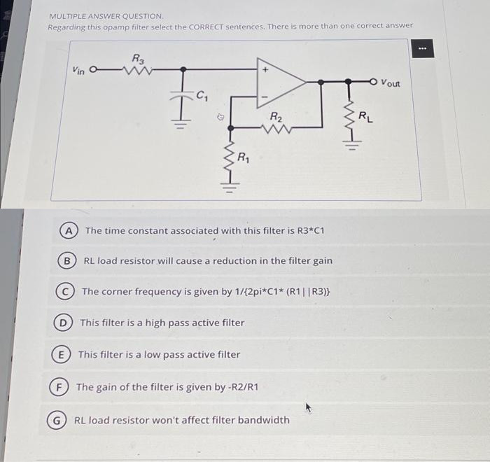

Transcribed Image Text:MULTIPLE ANSWER QUESTION.
Regarding this opamp filter select the CORRECT sentences. There is more than one correct answer
Vin
R3
I
C₁
R₁
A The time constant associated with this filter is R3*C1
R₂
B RL load resistor will cause a reduction in the filter gain
The corner frequency is given by 1/{2pi*C1* (R1||R3)}
This filter is a high pass active filter
E This filter is a low pass active filter
FThe gain of the filter is given by -R2/R1
G) RL load resistor won't affect filter bandwidth
RL
Vout
1
Expert Solution
This question has been solved!
Explore an expertly crafted, step-by-step solution for a thorough understanding of key concepts.

This is a popular solution

Trending nowThis is a popular solution!

Step by stepSolved in 3 steps with 1 images

Knowledge Booster


Learn more about
Need a deep-dive on the concept behind this application? Look no further. Learn more about this topic, electrical-engineering and related others by exploring similar questions and additional content below.Similar questions
- The circuit shown in the given figure is an active filter. Assume C=120 pF. Ro-184 kohm. R₁33 kohm, and R2 = 60 kohm. NOTE: This is a multi-part question. Once an answer is submitted, you will be unable to return to this part. 4-5 www 14 www R₂ 2 ww 644 Determine the cutoff frequencies. The cutoff frequencies w₁ and 2 are 896 106 rad/s and 5.55-105 red/s, respectively. HE -arrow_forwardQ a.) State 2 ad Vantagis OF Filter active Filter Over Passi ve A low Pass FiHir has a high cut -OFF FreQUency Is applied to the with Freauency of Fi = lo hHz , Fz=8.2 h42 b. OF S.4 KHz: An input sig nal F3 = 4.2 hHz that will be Filtered out F2-8.2 4H2 Signal reason and identiFy the outPut and Statearrow_forwardPlease solve with workarrow_forward
arrow_back_ios
arrow_forward_ios
Recommended textbooks for you
- Introductory Circuit Analysis (13th Edition)Electrical EngineeringISBN:9780133923605Author:Robert L. BoylestadPublisher:PEARSON
 Delmar's Standard Textbook Of ElectricityElectrical EngineeringISBN:9781337900348Author:Stephen L. HermanPublisher:Cengage Learning
 Programmable Logic ControllersElectrical EngineeringISBN:9780073373843Author:Frank D. PetruzellaPublisher:McGraw-Hill Education
  Fundamentals of Electric CircuitsElectrical EngineeringISBN:9780078028229Author:Charles K Alexander, Matthew SadikuPublisher:McGraw-Hill Education
 Electric Circuits. (11th Edition)Electrical EngineeringISBN:9780134746968Author:James W. Nilsson, Susan RiedelPublisher:PEARSON
 Engineering ElectromagneticsElectrical EngineeringISBN:9780078028151Author:Hayt, William H. (william Hart), Jr, BUCK, John A.Publisher:Mcgraw-hill Education,
Introductory Circuit Analysis (13th Edition)
Electrical Engineering
ISBN:9780133923605
Author:Robert L. Boylestad
Publisher:PEARSON
Delmar's Standard Textbook Of Electricity
Electrical Engineering
ISBN:9781337900348
Author:Stephen L. Herman
Publisher:Cengage Learning
Programmable Logic Controllers
Electrical Engineering
ISBN:9780073373843
Author:Frank D. Petruzella
Publisher:McGraw-Hill Education
Fundamentals of Electric Circuits
Electrical Engineering
ISBN:9780078028229
Author:Charles K Alexander, Matthew Sadiku
Publisher:McGraw-Hill Education
Electric Circuits. (11th Edition)
Electrical Engineering
ISBN:9780134746968
Author:James W. Nilsson, Susan Riedel
Publisher:PEARSON
Engineering Electromagnetics
Electrical Engineering
ISBN:9780078028151
Author:Hayt, William H. (william Hart), Jr, BUCK, John A.
Publisher:Mcgraw-hill Education,