
Introductory Circuit Analysis (13th Edition)
13th Edition
ISBN: 9780133923605
Author: Robert L. Boylestad
Publisher: PEARSON
expand_more
expand_more
format_list_bulleted
Related questions
Concept explainers
Question
Use Blackman’s theorem to find the expression for the output resistance of the MOS Wilson source .
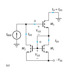

Transcribed Image Text:lo-Is
м,
VGs
IREF
Ipi
M2
M1
VGs
-o -Vss
(a)
Expert Solution
This question has been solved!
Explore an expertly crafted, step-by-step solution for a thorough understanding of key concepts.

Step by stepSolved in 2 steps with 6 images

Knowledge Booster


Learn more about
Need a deep-dive on the concept behind this application? Look no further. Learn more about this topic, electrical-engineering and related others by exploring similar questions and additional content below.Similar questions
- This question is about Mosfets as Amplifiers. Please help me with this. 6V VIN o VOUT RA It is given that the NMOS parameters are k, = 5A and VTH,n = 0.5V and the resistor RA = 1kN. Use AV = 2mV. Assume no channel length modulation. a.) Find the VTC of this amplifier. b.) Find the input bias voltage needed to achieve an output voltage of 3.0V and find the amplifier's gain at this bias condition. c.) Find the input bias voltage needed for maximum output voltage swing.arrow_forward1. The circuit below is a BJT Common Emitter Amplifier. Find Vout as a function of Vin. Redraw the circuit with the model for the BJT. (Power supply)arrow_forwardThe problem are DC analysis problems. For each of the circuits verify the mode of operation and solve for all applicable DC voltages and currents. > When you "verify" a mode of operation you will need to calculate all three voltages (Vc, Ve, VE for BJTS and VG, Vs, Vp for MOSFETS) and show the correct two conditions are satisfied. > Assume Capacitors acts like open circuits at DC and short circuits for AC. > Assume the following: o Beta = 100 O VBE = 0.7 o V: (Thermal) = 26 mV o V (Threshold) = 2V O VA = - o For MOSFET saturation mode: assume lp = K(Ves-Vr)? • (Assume K = 10 mA/V2). %3! 5V 1kn C2 2kn >10kn (C3 4mA -5Varrow_forward
- 5. For the circuit below, assume the MOSFET operates in saturation and is characterized by parameters VTN and KN. VINO- +VDD Rp OV OUT Rs Vss = -VDD a. Draw the equivalent circuit, replacing the MOSFET with its SCS model. b. Find the output operating point (V。 and I in terms of the input bias VIN) C. What is Vour when VIN=0? d. Draw the small-signal model e. Determine the small-signal gain Vout/Vin. f. Determine the small-signal output resistance g. Determine the small-signal input resistance.arrow_forwardDetermine the voltage gain for a NPN Emitter follower stage driven by a finite source impedance (without early effect) (You must derive every expression using the small-signal model method. Draw every circuit, show every equation)arrow_forwardElectrical Engineering Consider the emitter follower circuit below given Vcc=15V. VEE-15V, Rr. -1.8k, VBE 0.7V.VCE,aut = 0.2 V, and 8 = 100 for all the transistors. Find the value of resistor Rink? that will establish a blas current sufficiently large to allow the largest possible output voltage swing. Include the base currents for both Q₂ and Q₂. Please give your answer in two decimal places. Vcc 9 VEE VRE VERarrow_forward
- The problem are DC analysis problems. For each of the circuits verify the mode of operation and solve for all applicable DC voltages and currents. > When you "verify" a mode of operation you will need to calculate all three voltages (Vc, Ve, VE for BJTS and VG, Vs, Vp for MOSFETS) and show the correct two conditions are satisfied. > Assume Capacitors acts like open circuits at DC and short circuits for AC. > Assume the following: O Beta = 100 O VBE = 0.7 o V: (Thermal) = 26 mv o V (Threshold) = 2V O VA = -- o For MOSFET saturation mode: assume Ip = K(Ves-V-)? (Assume K = 10 mA/V²). 12V R2 1.0kn R1 100kn 01 R3 >1.0kn -12Varrow_forwardWhich of the following is a correct small signal model for a MOSFET? Gate Gate- Gate Gate Source Selected Coordinates Source www Source Source Source Drain Drain Drain Drainarrow_forwardCan you do 1.1 pleasearrow_forward
arrow_back_ios
arrow_forward_ios
Recommended textbooks for you
- Introductory Circuit Analysis (13th Edition)Electrical EngineeringISBN:9780133923605Author:Robert L. BoylestadPublisher:PEARSON
 Delmar's Standard Textbook Of ElectricityElectrical EngineeringISBN:9781337900348Author:Stephen L. HermanPublisher:Cengage Learning
 Programmable Logic ControllersElectrical EngineeringISBN:9780073373843Author:Frank D. PetruzellaPublisher:McGraw-Hill Education
  Fundamentals of Electric CircuitsElectrical EngineeringISBN:9780078028229Author:Charles K Alexander, Matthew SadikuPublisher:McGraw-Hill Education
 Electric Circuits. (11th Edition)Electrical EngineeringISBN:9780134746968Author:James W. Nilsson, Susan RiedelPublisher:PEARSON
 Engineering ElectromagneticsElectrical EngineeringISBN:9780078028151Author:Hayt, William H. (william Hart), Jr, BUCK, John A.Publisher:Mcgraw-hill Education,
Introductory Circuit Analysis (13th Edition)
Electrical Engineering
ISBN:9780133923605
Author:Robert L. Boylestad
Publisher:PEARSON
Delmar's Standard Textbook Of Electricity
Electrical Engineering
ISBN:9781337900348
Author:Stephen L. Herman
Publisher:Cengage Learning
Programmable Logic Controllers
Electrical Engineering
ISBN:9780073373843
Author:Frank D. Petruzella
Publisher:McGraw-Hill Education
Fundamentals of Electric Circuits
Electrical Engineering
ISBN:9780078028229
Author:Charles K Alexander, Matthew Sadiku
Publisher:McGraw-Hill Education
Electric Circuits. (11th Edition)
Electrical Engineering
ISBN:9780134746968
Author:James W. Nilsson, Susan Riedel
Publisher:PEARSON
Engineering Electromagnetics
Electrical Engineering
ISBN:9780078028151
Author:Hayt, William H. (william Hart), Jr, BUCK, John A.
Publisher:Mcgraw-hill Education,