
Introductory Circuit Analysis (13th Edition)
13th Edition
ISBN: 9780133923605
Author: Robert L. Boylestad
Publisher: PEARSON
expand_more
expand_more
format_list_bulleted
Related questions
Concept explainers
Question
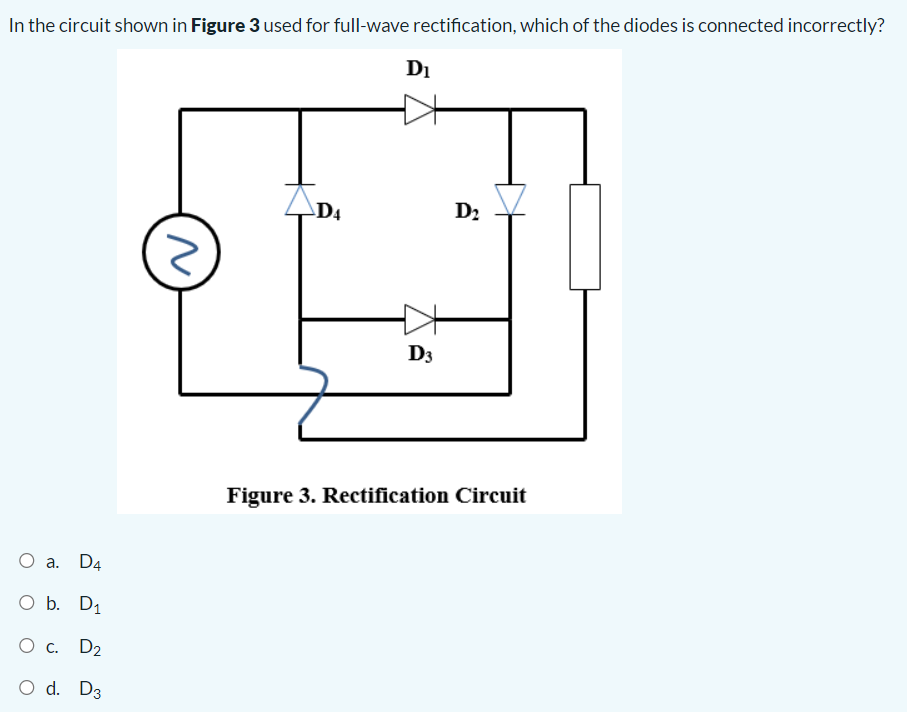

Transcribed Image Text:In the circuit shown in Figure 3 used for full-wave rectification, which of the diodes is connected incorrectly?
O a. D4
O b. D₁
O c. D₂
O d. D3
z
D4
D₁
D3
D₂
Figure 3. Rectification Circuit
Expert Solution
This question has been solved!
Explore an expertly crafted, step-by-step solution for a thorough understanding of key concepts.

This is a popular solution

Trending nowThis is a popular solution!

Step by stepSolved in 3 steps with 2 images

Knowledge Booster


Learn more about
Need a deep-dive on the concept behind this application? Look no further. Learn more about this topic, electrical-engineering and related others by exploring similar questions and additional content below.Similar questions
- 3. An SCR differs from the Shockley diode because a. it has a gate terminal b. it is not a thyristor c. it does not have four layers d. it cannot be turned on and off 4. A Shockley diode turns on when the anode to cathode voltage a. exceeds 0.7 V b. exceeds the gate voltage c. exceeds the forward-breakover voltage d. exceeds the forward-blocking voltage 5. Once it is conduction, a Shockley diode can be turned off by a. reducing the current below a certain value b. disconnecting the anode voltage c. a and b d. none of thesearrow_forwardQ2: Draw the output waveform for the three shown circuits. 1- +10 V 1Ok V. 0- 5 V 5 V -10V Diodes are IN914. 2- Assume Vm=20V, show the Vdc on the graph D 3- Assume VM3D18V and V-5V. 34arrow_forwardR₁ 54 R₂ D₁ ▷ Figure 1: Precision Rectifier 1. Characterize the relationship of input vs. output for the circuit in Figure 1. That is, find an expression for e. You can use the constant voltage drop model for the diodes. VIarrow_forward
- If one of the diodes in the figure below is open, the average voltage across the load is:(a) increases (b) decreases (c) does not changearrow_forwardFor the tollowing shaping cir cuits, sketch vo. wave Show your analysis. Label Vo' :consider ideal diodes. RI NOte 个 20v R2 SK Rz F2,5k Vo 5K -20varrow_forwardFind the current I if both diodes are identical. Voltage V = 0.8V and let the reverse saturation current be 10-⁹A. D1 D2arrow_forward
arrow_back_ios
arrow_forward_ios
Recommended textbooks for you
- Introductory Circuit Analysis (13th Edition)Electrical EngineeringISBN:9780133923605Author:Robert L. BoylestadPublisher:PEARSON
 Delmar's Standard Textbook Of ElectricityElectrical EngineeringISBN:9781337900348Author:Stephen L. HermanPublisher:Cengage Learning
 Programmable Logic ControllersElectrical EngineeringISBN:9780073373843Author:Frank D. PetruzellaPublisher:McGraw-Hill Education
  Fundamentals of Electric CircuitsElectrical EngineeringISBN:9780078028229Author:Charles K Alexander, Matthew SadikuPublisher:McGraw-Hill Education
 Electric Circuits. (11th Edition)Electrical EngineeringISBN:9780134746968Author:James W. Nilsson, Susan RiedelPublisher:PEARSON
 Engineering ElectromagneticsElectrical EngineeringISBN:9780078028151Author:Hayt, William H. (william Hart), Jr, BUCK, John A.Publisher:Mcgraw-hill Education,
Introductory Circuit Analysis (13th Edition)
Electrical Engineering
ISBN:9780133923605
Author:Robert L. Boylestad
Publisher:PEARSON
Delmar's Standard Textbook Of Electricity
Electrical Engineering
ISBN:9781337900348
Author:Stephen L. Herman
Publisher:Cengage Learning
Programmable Logic Controllers
Electrical Engineering
ISBN:9780073373843
Author:Frank D. Petruzella
Publisher:McGraw-Hill Education
Fundamentals of Electric Circuits
Electrical Engineering
ISBN:9780078028229
Author:Charles K Alexander, Matthew Sadiku
Publisher:McGraw-Hill Education
Electric Circuits. (11th Edition)
Electrical Engineering
ISBN:9780134746968
Author:James W. Nilsson, Susan Riedel
Publisher:PEARSON
Engineering Electromagnetics
Electrical Engineering
ISBN:9780078028151
Author:Hayt, William H. (william Hart), Jr, BUCK, John A.
Publisher:Mcgraw-hill Education,