Introductory Circuit Analysis (13th Edition)
13th Edition
ISBN: 9780133923605
Author: Robert L. Boylestad
Publisher: PEARSON
expand_more
expand_more
format_list_bulleted
Concept explainers
Question
please help me with this question, thanks

Transcribed Image Text:### Transcription and Explanation for Educational Purposes
#### Text Transcription:
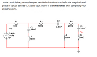
"In the circuit below, please show your detailed calculations to solve for the magnitude and phase of voltage at node \(V_o\). Express your answer in the **time domain** after completing your phasor analysis."
#### Circuit Diagram Description:
The circuit consists of the following components:
- **Source \(V_1\):**
- Voltage: 5 V peak (Vpk)
- Frequency: 1 kHz
- Phase: 0°
- **Resistors:**
- \(R_1 = 50 \, \Omega\)
- \(R_2 = 100 \, \Omega\)
- \(R_4 = 200 \, \Omega\)
- \(R_3 = 100 \, \Omega\)
- **Capacitors:**
- \(C_1 = 3.9 \, \text{nF} \)
- \(C_2 = 3.9 \, \text{nF} \)
- \(C_3 = 7.8 \, \text{nF} \)
- **Inductors:**
- \(L_1 = 310 \, \text{mH} \)
- \(L_2 = 310 \, \text{mH} \)
- **Output Voltage \(V_o\):**
- Node \(V_o\) is located at the connection between \(R_3\), \(C_3\), and \(R_4\).
#### Explanation:
The task involves analyzing the given RLC circuit to determine the magnitude and phase of the voltage at node \(V_o\). The analysis starts by using phasor representation to handle the sinusoidal inputs and reactive components.
Steps to perform the analysis:
1. **Impedance Calculations:**
- Determine the impedance of each capacitor and inductor at the given frequency (1 kHz).
- Capacitive impedance: \( Z_C = \frac{1}{j \omega C} \)
- Inductive impedance: \( Z_L = j \omega L \)
2. **Phasor Analysis:**
- Apply Kirchhoff's laws and use impedance values to solve for voltages or currents in the phasor domain.
3. **Convert Results to Time Domain:**

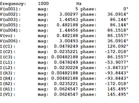
Transcribed Image Text:This image contains data from an electrical circuit analysis at a frequency of 1000 Hz. The table lists various nodes and components with their respective magnitude (mag) and phase values in degrees.
1. **Frequency**: 1000 Hz
2. **Nodes and Components**:
- **V(n001)**:
- Magnitude: 5
- Phase: 0°
- **V(n002)**:
- Magnitude: 3.00297
- Phase: 36.0914°
- **V(n003)**:
- Magnitude: 1.44656
- Phase: 86.144°
- **V(n005)**:
- Magnitude: 0.482188
- Phase: 86.144°
- **V(n004)**:
- Magnitude: 1.44656
- Phase: 86.1518°
- **V(vo)**:
- Magnitude: 0.482188
- Phase: 86.1557°
- **V(n006)**:
- Magnitude: 3.00493
- Phase: 36.0914°
- **I(C1)**:
- Magnitude: 0.0478249
- Phase: -126.092°
- **I(C2)**:
- Magnitude: 0.0235221
- Phase: -172.018°
- **I(C3)**:
- Magnitude: 0.00482188
- Phase: 86.1557°
- **I(L1)**:
- Magnitude: 0.0478249
- Phase: -53.9077°
- **I(R2)**:
- Magnitude: 0.0230228
- Phase: -3.84733°
- **I(R4)**:
- Magnitude: 0.00482188
- Phase: -93.8443°
- **I(R1)**:
- Magnitude: 0.0235221
- Phase: -172.018°
- **I(R3)**:
- Magnitude: 0.0624547
- Phase: 145.495°
- **I(V1)**
Expert Solution
This question has been solved!
Explore an expertly crafted, step-by-step solution for a thorough understanding of key concepts.
Step by stepSolved in 6 steps with 1 images

Knowledge Booster
Learn more about
Need a deep-dive on the concept behind this application? Look no further. Learn more about this topic, electrical-engineering and related others by exploring similar questions and additional content below.Similar questions
- can you please help me on a home work question. havent worked with this stuff in 47 yearsarrow_forwardPlease send the answer by typing only. I don't want handwritten. The subject is about Renewable Energy ( Fossil Fuels) 3. How the Fossil Fuels are contributing to global warming?arrow_forwardPlease send the answer by typing only. I don't want handwritten. The subject is about Renewable Energy ( Fossil Fuels) 7. What are the advantages and disadvantages of Fossil Fuels?arrow_forward
arrow_back_ios
arrow_forward_ios
Recommended textbooks for you
 Introductory Circuit Analysis (13th Edition)Electrical EngineeringISBN:9780133923605Author:Robert L. BoylestadPublisher:PEARSON
 Delmar's Standard Textbook Of ElectricityElectrical EngineeringISBN:9781337900348Author:Stephen L. HermanPublisher:Cengage Learning
 Programmable Logic ControllersElectrical EngineeringISBN:9780073373843Author:Frank D. PetruzellaPublisher:McGraw-Hill Education
 Fundamentals of Electric CircuitsElectrical EngineeringISBN:9780078028229Author:Charles K Alexander, Matthew SadikuPublisher:McGraw-Hill Education
 Electric Circuits. (11th Edition)Electrical EngineeringISBN:9780134746968Author:James W. Nilsson, Susan RiedelPublisher:PEARSON
 Engineering ElectromagneticsElectrical EngineeringISBN:9780078028151Author:Hayt, William H. (william Hart), Jr, BUCK, John A.Publisher:Mcgraw-hill Education,

Introductory Circuit Analysis (13th Edition)
Electrical Engineering
ISBN:9780133923605
Author:Robert L. Boylestad
Publisher:PEARSON

Delmar's Standard Textbook Of Electricity
Electrical Engineering
ISBN:9781337900348
Author:Stephen L. Herman
Publisher:Cengage Learning

Programmable Logic Controllers
Electrical Engineering
ISBN:9780073373843
Author:Frank D. Petruzella
Publisher:McGraw-Hill Education

Fundamentals of Electric Circuits
Electrical Engineering
ISBN:9780078028229
Author:Charles K Alexander, Matthew Sadiku
Publisher:McGraw-Hill Education

Electric Circuits. (11th Edition)
Electrical Engineering
ISBN:9780134746968
Author:James W. Nilsson, Susan Riedel
Publisher:PEARSON

Engineering Electromagnetics
Electrical Engineering
ISBN:9780078028151
Author:Hayt, William H. (william Hart), Jr, BUCK, John A.
Publisher:Mcgraw-hill Education,