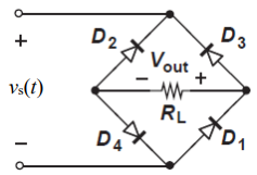
While constructing a Bridge rectifier, the designer mistakenly has swapped the terminals of D3 as shown in the figure below, where
• Diode D3 is damaged so that it is always open circuit regardless of the applied voltage.
• vs(t) is a sinusoidal signal with a peak value (Vs = 5 V).
• Diodes are modelled using the constant voltage model with VDO = 0.7 V
• The ac line voltage has an rms value of 120 V and a frequency (f) = 60 Hz
• The resistance RL = 10 kohm.
a) Calculate the transformer turns ratio (N1/N2) if vs(t) is obtained from the secondary side of the transformer whose primary side is connected to the ac line voltage (which has a 120 V rms value).
b) Plot in the same graph the input signal vs(t) and the output signal vout(t) (show all details including amplitudes, time instances, etc.)
c) Calculate the rms values of the output signal vout(t). (hint: sin2 (x) = 0.5(1- cos(2x)))
d) If a capacitor C = 3.58 µF is connected across R = 10 kohm, repeat (b) in a new graph
e) With the capacitor C = 3.58 µF is connected across R = 10 kohm, determine the peak-to-peak ripple voltage (Vr) and the conduction angle (ωΔt).

Step by stepSolved in 4 steps with 1 images

Could you help me to plot the graph, please?
Could you help me to plot the graph, please?
- This about PN Junctions of semiconductors.arrow_forwardOne component that does not need to be installed in the correct orientation is a: a. Resistorb. Diodec. Voltage regulatord.arrow_forwardA 3-phase full-wave bridge rectifier is built using six power diodes numbered 1 to 6. The phase sequence of the 3-phase source is ABC and the line to line voltage is 440 V. The line to neutral voltage of phase A has an angle of -30 degrees. The anodes of the diodes 1, 2, 3 are connected to phase A, B, and C, respectively, and the cathodes of diodes 1, 2, and 3 are connected to a common terminal that serves as the positive terminal of the rectifier's output. The cathodes of diodes 4, 5, and 6 are connected to phase A, B, and C, respectively, and the anodes of diodes 4, 5, and 6 are connected to a common terminal that serves as the negative terminal of the rectifier's output. If diode 1 is damaged and acts as an open circuit, what would the RMS voltage be at the load?arrow_forward
- For the circuit shown below, sketch to scale the output V waveform and draw the transfer characteristic (V versus Vi), Assume the diodes are ideal.arrow_forwardFor the circuit in the figure, let V input = 8V, Ri = 12ohms, RL = 10ohms, and VZ = 3.3V. Determine the voltages and currents of the resistors and the current of the zener diode.arrow_forwardDetermine which diodes are forward-biased and which are reverse-biased in the configurations.. Assuming a 0.7-V drop across each forward-biased diode, determine the output voltage.arrow_forward
- The four diodes used in a bridge rectifier circuit have forward resistances which may be considered constant at 1 ohm and infinite reverse resistance. The alternating supply voltage is 220 V r.m.s. and load resistance is 580 ohm. Calculate (i) mean load current and (ii) power dissipated in each diode.arrow_forward4.) In which mode will a diode generally not conduct electricity? a. Bidirectional Biased b. None of these c. Forward Biased d. Reversed Biased 5.) Consider the following schematic symbol of a semiconductor device: Which side is the Cathode? (Picture inserted down below) a. Side A b. Both side A and B c. Side B d. Neither side A or B 8.) Integrated circuits can be broken down into three basic categories. Which category does an operational amplifier (or op-amp) fall into? a. Analog b. None of these c. A combination of analog and digital d. Digitalarrow_forwardAnswer a,b,c,darrow_forward
- . A half-wave rectifier is needed to supply 15-V dc to a load that draws an average current of 300 mA. The peak-to-peak ripple is required to be 0.2 V or less. What is the minimum value allowed for the smoothing capacitance?arrow_forwardone SCR in anti parallel with firing angel of 90° for the 30. A single-phase voltage controller, using a diode, feeds a load R and Vs = 230 V. For a SCR, the PMMC voltage connected across R would readarrow_forward
 Introductory Circuit Analysis (13th Edition)Electrical EngineeringISBN:9780133923605Author:Robert L. BoylestadPublisher:PEARSON
 Delmar's Standard Textbook Of ElectricityElectrical EngineeringISBN:9781337900348Author:Stephen L. HermanPublisher:Cengage Learning
 Programmable Logic ControllersElectrical EngineeringISBN:9780073373843Author:Frank D. PetruzellaPublisher:McGraw-Hill Education
 Fundamentals of Electric CircuitsElectrical EngineeringISBN:9780078028229Author:Charles K Alexander, Matthew SadikuPublisher:McGraw-Hill Education
 Electric Circuits. (11th Edition)Electrical EngineeringISBN:9780134746968Author:James W. Nilsson, Susan RiedelPublisher:PEARSON
 Engineering ElectromagneticsElectrical EngineeringISBN:9780078028151Author:Hayt, William H. (william Hart), Jr, BUCK, John A.Publisher:Mcgraw-hill Education,


