
Power System Analysis and Design (MindTap Course List)
6th Edition
ISBN: 9781305632134
Author: J. Duncan Glover, Thomas Overbye, Mulukutla S. Sarma
Publisher: Cengage Learning
expand_more
expand_more
format_list_bulleted
Related questions
Concept explainers
Question
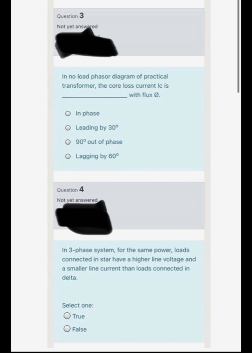

Transcribed Image Text:Question 3
Not yet answered
In no load phasor diagram of practical
transformer, the core loss current Ic is
with flux Ø.
O In phase
O Leading by 30°
O 90° out of phase
O Lagging by 60°
Question 4
Not yet answered
In 3-phase system, for the same power, loads
connected in star have a higher line voltage and
a smaller line current than loads connected in
delta.
Select one:
O True
O False
Expert Solution
This question has been solved!
Explore an expertly crafted, step-by-step solution for a thorough understanding of key concepts.

Step by stepSolved in 2 steps with 2 images

Knowledge Booster


Learn more about
Need a deep-dive on the concept behind this application? Look no further. Learn more about this topic, electrical-engineering and related others by exploring similar questions and additional content below.Similar questions
- Show me how is solution will be if fualt happened before transformers or in one of generatorarrow_forwardPlease solve d, e, f ONLY.arrow_forwardThe one-line diagram of a simple power system is shown in Figure below. The neutral of each generator is grounded through a current-limiting reactor of 0.25/3 per unit on a 100-MVA base. The system data expressed in per unit on a common 100-MVA base is tabulated below. The generators are running on no-load at their rated voltage and rated frequency with their emfs in phase. G Stark Item Base MVA Voltage Rating X' x² 20 kV 20 kV 20/220 kV 20/220 kV 100 0.05 0.15 0.15 0.10 0.10 220 kV 0.125 0.125 0.30 0.15 0.25 025 0.7125 0.15 100 100 0.15 0.05 0.10 0.10 0.10 100 0.10 100 100 Lu La 220 kV 0.15 220 kV 0.35 100 A balanced three-phase fault at bus 3 through a fault impedance Zf= jo.I per unit. The magnitude of the fault current in amperes in phase b for this fault is: Select one: A. 345.3 B. 820.1 C. 312500 3888888 产产arrow_forward
- TRUE or FALSE: If a transformer is loaded from full-load value to half-load value, then the amount of core loss is also halved.arrow_forwardProblem 1 - Series en Parallel AC networks [19] Look at the circuit in Figure 1 and determine the following: (a) Total Admittance. (b) Total Impedance. (c) Total Current (l:). (d) Current (I1) through impedance Z2. (e) Current (12) through impedance Z3. (f) Current (I3) through impedance Z4. (g) Is this an inductive or capacitive circuit? A. B Zs 220V;50HZ Figure 1 (h) Voltage across Z1. (i) Voltage across A and B. G) Voltage across Zs. Z1 = 3 + j5 ohm Z2 = 10 + jo ohm Z3 = 5 + j15 ohm Z4 = 10 – j30 ohm Zs = 20 – j30 ohm Admittance and Impedance in rectangular notation. All currents and voltage in polar notation. Take voltage as reference.arrow_forwardNEAT EXPLAIN NEEDED( CORRECT ANSWER NO GPT PLEASE)arrow_forward
- Determine the positive- and negative-sequence phase shifts for the three- phase transformers shown in Figure 3.36.arrow_forwardThree single-phase two-winding transformers, each rated 3kVA,220/110volts,60Hz, with a 0.10 per-unit leakage reactance, are connected as a three-phase extended autotransformer bank, as shown in Figure 3.36(c). The low-voltage winding has a 110 volt rating. (a) Draw the positive-sequence phasor diagram and show that the high-voltage winding has a 479.5 volt rating. (b) A three-phase load connected to the low-voltage terminals absorbs 6 kW at 110 volts and at 0.8 power factor lagging. Draw the per-unit impedance diagram and calculate the voltage and current at the high-voltage terminals. Assume positive-sequence operation.arrow_forwardHow many transformers are needed to make an open-delta connection?arrow_forward
- Please, I do not want a theoretical solution or using artificial intelligence. I want a solution on paper using the mathematical laws of the topicarrow_forwardHigh voltage engineering subjectarrow_forwardFind the following : 1.Ripple Voltage (vpp) 2. Zero-to peak ripple(Vop) 3.secondary winding of the transformer high line and low linearrow_forward
arrow_back_ios
SEE MORE QUESTIONS
arrow_forward_ios
Recommended textbooks for you
- Power System Analysis and Design (MindTap Course ...Electrical EngineeringISBN:9781305632134Author:J. Duncan Glover, Thomas Overbye, Mulukutla S. SarmaPublisher:Cengage Learning
 Delmar's Standard Textbook Of ElectricityElectrical EngineeringISBN:9781337900348Author:Stephen L. HermanPublisher:Cengage Learning
Power System Analysis and Design (MindTap Course ...
Electrical Engineering
ISBN:9781305632134
Author:J. Duncan Glover, Thomas Overbye, Mulukutla S. Sarma
Publisher:Cengage Learning
Delmar's Standard Textbook Of Electricity
Electrical Engineering
ISBN:9781337900348
Author:Stephen L. Herman
Publisher:Cengage Learning