
Introductory Circuit Analysis (13th Edition)
13th Edition
ISBN: 9780133923605
Author: Robert L. Boylestad
Publisher: PEARSON
expand_more
expand_more
format_list_bulleted
Related questions
Question
Solve by hand not using AI or chat gpt
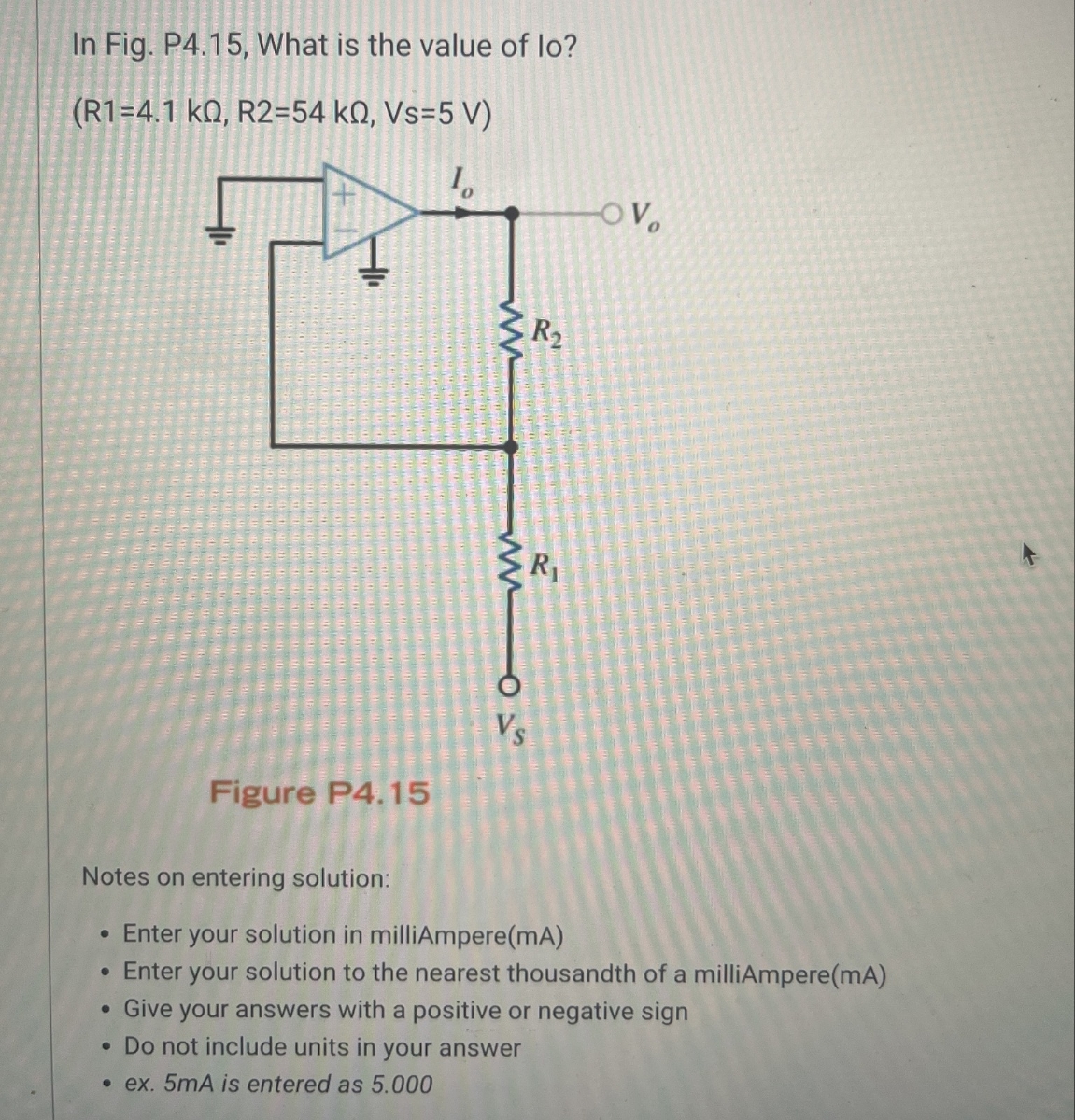

Transcribed Image Text:In Fig. P4.15, What is the value of lo?
(R1=4.1 kQ, R2=54 kQ, Vs=5 V)
10
www
OV
R2
R₁
www
015
Figure P4.15
Notes on entering solution:
.
Enter your solution in milliAmpere(mA)
• Enter your solution to the nearest thousandth of a milliAmpere(mA)
Give your answers with a positive or negative sign
• Do not include units in your answer
.ex. 5mA is entered as 5.000
Expert Solution
This question has been solved!
Explore an expertly crafted, step-by-step solution for a thorough understanding of key concepts.

Step by stepSolved in 2 steps with 2 images

Knowledge Booster

Similar questions
- Please show all work, thank you :)arrow_forwardFor the diode circuit to the right 8002 a V' V 40mA (T 1002 0.001V' a) To the left of points a and b, find the load-line relation by expressing the current, I with voltage, V. HINT: Write KCL equation for the circuit diagram and write I in terms of V from that KCL equation. This will be your load-line equation.arrow_forwardFor the diode circuit to the right 8002 a V 1002 b 40mA 0.001V' a) To the left of points a and b, find the load-line relation by expressing the current, I with voltage, V. HINT: Write KCL equation for the circuit diagram and write I in terms of V from that KCL equation. This will be your load-line equation. b) Assume the diode has the following characteristic, using the load-line relation you found in (a), determine the operating voltage, V and current, I for the circuit. ip (mA) 20 15 10 5 Vp (V) 3.0 0.5 '1.0 1.5 2.0 2.5arrow_forward
- For the last two parts, use the diagram to the right. d. V = -1.14V, R = 62, and the voltage across the diode is equal to 0.68V when it is "on". i V = e. V = -0.16V, R = 52, and the voltage across the diode is equal to 0.64V when it is "on". V= i = Vo ww R≤ KHI (Enter at least 3 significant digits. Each answer must be within 1% to be marked correct.) + ひ -arrow_forwardA diode is a two-terminal, electronic device made using semiconductors that is designed to prevent current from flowing in a particular direction. The symbol is a triangle pointing in the direction that (positive) current is allowed to flow and a wall preventing (positive) current from flowing in the opposite direction: 1: A diode has two modes, "on" and "off". When "on", current flows, and when "off", no current flows. We generally view diodes as either "ideal" or "modeled", as described below. "Ideal" view of a diode + The "ideal" diode is either a short circuit or an open circuit. Specifically, when the voltage across its terminals is negative, no current flows, and when current flows, there is zero voltage across its terminals, as pictured below: Diode "Modeled" view of a diode +51 Diode V Ideal Diode "Off" i=0| + U≤0 + I Therefore, with current i and voltage v defined as shown on the left above, for an "ideal" diode: • Current i cannot be negative. Voltage v cannot be positive. .…arrow_forwardQ2: Solve for only one of the followings: A\ Determine ID1, ID2, VD1 and VD2, using ideal diode model 15 Q 10 V 10Q W- W- + Vp2 30ias. 15 V Rhimt 20 V B\ Assume D1 and D2 are Si diodes. Find ID1, ID2, VD1, VD2 and IO in the circuit below, the practical model. IDI Ip: W- 52 + Vpi - RLimb lo sa 10 V Q3\A: Determine the values of VDC, Vr(out) , and IL for the power supply shown belo Explain whether we can use the Zener diode in this circuit as the voltage regulator or not? رقم الصفحة 2/1arrow_forward
- THIS IS URGENT PLEASE ANSWER THANKSarrow_forwardA silicon diode described by the Shockley equation has n = 2 and operates at 150° C with a current of 1 mA and voltage of 0.25 V. Part A Determine the current after the voltage is increased to 0.32 V. Express your answer to three significant figures and include the appropriate units. HA ? ip = Value Unitsarrow_forwardPlease help prove the 3 equations in the second attached image.arrow_forward
- Hello, a step by step guide would be greatly appreciated. Please follow the NOTES & SUGGESTIONS at the bottom when solving, answering what is asked as I need to understand doing it and checking/verifying results, and show every step for understanding, thanks so much :)arrow_forwardPlease answer thanksarrow_forwardPlease answer in typing format I need it urgently I will like it please Please ASAP for the likearrow_forward
arrow_back_ios
SEE MORE QUESTIONS
arrow_forward_ios
Recommended textbooks for you
- Introductory Circuit Analysis (13th Edition)Electrical EngineeringISBN:9780133923605Author:Robert L. BoylestadPublisher:PEARSON
 Delmar's Standard Textbook Of ElectricityElectrical EngineeringISBN:9781337900348Author:Stephen L. HermanPublisher:Cengage Learning
 Programmable Logic ControllersElectrical EngineeringISBN:9780073373843Author:Frank D. PetruzellaPublisher:McGraw-Hill Education
  Fundamentals of Electric CircuitsElectrical EngineeringISBN:9780078028229Author:Charles K Alexander, Matthew SadikuPublisher:McGraw-Hill Education
 Electric Circuits. (11th Edition)Electrical EngineeringISBN:9780134746968Author:James W. Nilsson, Susan RiedelPublisher:PEARSON
 Engineering ElectromagneticsElectrical EngineeringISBN:9780078028151Author:Hayt, William H. (william Hart), Jr, BUCK, John A.Publisher:Mcgraw-hill Education,
Introductory Circuit Analysis (13th Edition)
Electrical Engineering
ISBN:9780133923605
Author:Robert L. Boylestad
Publisher:PEARSON
Delmar's Standard Textbook Of Electricity
Electrical Engineering
ISBN:9781337900348
Author:Stephen L. Herman
Publisher:Cengage Learning
Programmable Logic Controllers
Electrical Engineering
ISBN:9780073373843
Author:Frank D. Petruzella
Publisher:McGraw-Hill Education
Fundamentals of Electric Circuits
Electrical Engineering
ISBN:9780078028229
Author:Charles K Alexander, Matthew Sadiku
Publisher:McGraw-Hill Education
Electric Circuits. (11th Edition)
Electrical Engineering
ISBN:9780134746968
Author:James W. Nilsson, Susan Riedel
Publisher:PEARSON
Engineering Electromagnetics
Electrical Engineering
ISBN:9780078028151
Author:Hayt, William H. (william Hart), Jr, BUCK, John A.
Publisher:Mcgraw-hill Education,