Question

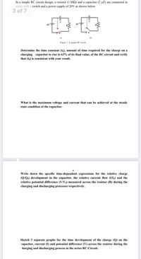
Transcribed Image Text:In a simple RC circuit design, a resistor (1 MQ) and a capacitor (2 µF) are connected in
series with a switch and a power supply of 20V as shown below.
3 of 7
AVT
(a)
(b)
Figure 1: A simple RC circuit
Determine the time constant (to), amount of time required for the charge on a
charging capacitor to rise to 63% of its final value, of the RC-circuit and verify
that (to) is consistent with your result.
What is the maximum voltage and current that can be achieved at the steady
state condition of the capacitor.
Write down the specific time-dependent expressions for the relative charge
(Q/Q.) development in the capacitor, the relative current flow (I/I,) and the
relative potential difference (V/V) measured across the resistor (R) during the
charging and discharging processes respectively.
Sketch 3 separate graphs for the time development of the charge (Q) on the
capacitor, current (I) and potential difference (V) across the resistor during the
harging and discharging process in the series RC-Circuit.
Expert Solution
This question has been solved!
Explore an expertly crafted, step-by-step solution for a thorough understanding of key concepts.
This is a popular solution
Trending nowThis is a popular solution!
Step by stepSolved in 5 steps with 5 images

Knowledge Booster
Similar questions
- please answer vvvarrow_forwardA series RC circuit consist of a 502 resistor, a 15uF capacitor and a switch 1. that is initial open and then closed at time t 0, all connected in series to a 15V battery Determine the time constant of the circuit (a) (b) Find the initial current when the switch is initially closed at time t = 0. Find the charge on the capacitor after a long period of time (c)arrow_forwardA 93uF capacitor Initially uncharged, is connected in a series with a 7kO resistor, and this combination is connected across and ideal 12V DC battery. As the capacitor charges, What is the current in the circuit as the capacitor reaches 17% of it maximum charge. What is the voltage across the resister when the capacitor is 17% charhed. How much charge is accumilated on the capacitor after three times constantsarrow_forward
- The RC charging circuit in a camera flash unit has a voltage source of 265 V and a capacitance of 111 µF. HINT (a) Find its resistance R (in ohms) if the capacitor charges to 90.0% of its final value in 16.7 s. (b) Find the average current (in A) delivered to the flash bulb if the capacitor discharges 90.0% of its full charge in 1.54 ms. Aarrow_forwardThe RC charging circuit in a camera flash unit has a voltage source of 255 V and a capacitance of 116 µF. HINT (a) Find its resistance R (in ohms) if the capacitor charges to 90.0% of its final value in 16.2 s. Ω (b) Find the average current (in A) delivered to the flash bulb the capacitor discharges 90.0% of its full charge in 1.34 ms. Aarrow_forwardA 120-Ohm resistor is in series with unknown resistor. The voltage drop across the unknown resistor is 12V and power dissipated b the 120-Ohm resistor is 4.8W. calculate the value of unknown resistor.arrow_forward
- A capacitor of 7.99 µF is discharged through a resistor of resistance R. The time constant of the discharge is 5.6 space cross times space 10 to the power of negative 3 end exponent s Calculate the value of R.arrow_forwardImagine that we had a RC circuit with a 19.2 kilo-ohm resistor connected in parallel with a 16 kilo-ohm resistor and they were connected to two capacitors (404.2 uF, 350.1 uF) that are in series. What is the time constant of this circuit?arrow_forwardHow long (in s) will it take an RC circuit made with a 50 O resistor and a 20 mF capacitor to lose half its initial charge? Give your answer as only the numerical value in the SI units specified. e is interpreted as x10^ for use with large or small values; 1.01e2 is interpreted as 1.01 x 102.arrow_forward
- In an experiment, an initially uncharged capacitor of capacitance C=62µF (microFarad) is connected to a resistor R and a battery of voltage V as shown in the figure below: V(V) VT After the switch is closed at t=0, the voltage across the capacitor is measured and plotted as shown in the figure below. Using the data provided in the curve, determine the value of resistance R. Express your answer in units of using zero decimal places. 13- 12- 11 10- 9 8- 7- 6 5 4- 3 2 1- 0- 0 P 0.1 66****** 0.2 0.3 R www 0.4 0.5 C 0.6 t (s) 0.7 0.8 0.9 1 1.1 1.2 4arrow_forwardagle - Yahoo Searc... 0 Figure In (Figure 1), the total resistance is 20.0 kf, and the battery's emf is 33.0 V. The time constant is measured to be 12.0 μs Ris Take Test: PHY1200-... + R ww E S C 1 of 1 > openvellum.ecollege.com https://www.prometric... Submit Part B ✓ Correct t = 7.96 y pearson login - Yahoo.. Submit Previous Answers Provide Feedback Calculate the time it takes for the voltage across the resistor to reach 16.0 V after the switch is closed. Express your answer to three significant figures and include the appropriate units. μA Ω % A C μS Pearson Previous Answers Request Answer * Incorrect; Try Again; 2 attempts remaining ? Course Home 1 y cunyfirst login - Yaho... Review I Constants Copyright © 2022 Pearson Education Inc. All rights reserved. | Terms of Use | Privacy Policy | Permissions Contact Us | Next >arrow_forwardUsing the exact exponential treatment, find how much time is required to discharge a 268-µF capacitor through a 498-Ω resistor down to 1.00% of its original voltage?____ sarrow_forward
arrow_back_ios
SEE MORE QUESTIONS
arrow_forward_ios