Introductory Circuit Analysis (13th Edition)
13th Edition
ISBN: 9780133923605
Author: Robert L. Boylestad
Publisher: PEARSON
expand_more
expand_more
format_list_bulleted
Question
thumb_up100%
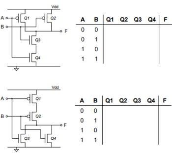
How would I complete the truth tables for these logic gates? How do I know whether the transistor is closed (c) or open (o) for each '1' or '0' as listed for F outputs?

Transcribed Image Text:A
Во
A
Bo
d
Q1
Q3
Q3
Q4
Q1
Q2
Vdd
Q2
Vdd
Q4
F
OF
A B Q1 Q2 Q3 Q4 F
Q4
0
0
0
1
1
0
1
1
A B Q1 Q2 Q3 Q4 F
0
0
1
0
1
0
1
1
Expert Solution
This question has been solved!
Explore an expertly crafted, step-by-step solution for a thorough understanding of key concepts.
Step by stepSolved in 3 steps with 1 images

Knowledge Booster
Learn more about
Need a deep-dive on the concept behind this application? Look no further. Learn more about this topic, electrical-engineering and related others by exploring similar questions and additional content below.Similar questions
- Design an exclusive nor (XNOR) gate using only 74HC02 NOR gates. (Pin outs shown below). Complete your design by first drawing the truth table for the XNOR gate, simplify, and then draw the logic including pin numbers, Vec and ground for the dual inline package. This is to be a build ready design. Be sure to account for unused gates.arrow_forwardPlease do part b using the Assumptionarrow_forwardImplement the logic circuit in Figure 2 using only NAND gate A B C Xarrow_forward
- 5 Note: Please do not handwritten.arrow_forward30) Coils labeled ( S ) and ( R )A) must appear in that order (S before R) in a ladder logic programB) may be used only in subroutines in programs for Siemens PLCsC) are Short and Repeated coils, used in timing programsD) may be used instead of a seal-in arrangement to provide latchingarrow_forwardDesign a " 2 to 4" Decoder with SEL' (active lo) 1. Generate the logic gates and the equations 2. Draw the timing waveforms for all inputs/SEL and output. 3. Create an application that could use this simple Decoderarrow_forward
- Sketch a circuit to represent the logic AB’C’D using a. a conventional symbol b. an array logic symbol.arrow_forwardwhat is the relation bet are the relations be Carry Out outputs of figures in step 3 and step 4? What is the relation between inputs & the sum output in half adder? What is the purpose of half adder and full adder logic circuits? fullarrow_forward
arrow_back_ios
arrow_forward_ios
Recommended textbooks for you
 Introductory Circuit Analysis (13th Edition)Electrical EngineeringISBN:9780133923605Author:Robert L. BoylestadPublisher:PEARSON
 Delmar's Standard Textbook Of ElectricityElectrical EngineeringISBN:9781337900348Author:Stephen L. HermanPublisher:Cengage Learning
 Programmable Logic ControllersElectrical EngineeringISBN:9780073373843Author:Frank D. PetruzellaPublisher:McGraw-Hill Education
 Fundamentals of Electric CircuitsElectrical EngineeringISBN:9780078028229Author:Charles K Alexander, Matthew SadikuPublisher:McGraw-Hill Education
 Electric Circuits. (11th Edition)Electrical EngineeringISBN:9780134746968Author:James W. Nilsson, Susan RiedelPublisher:PEARSON
 Engineering ElectromagneticsElectrical EngineeringISBN:9780078028151Author:Hayt, William H. (william Hart), Jr, BUCK, John A.Publisher:Mcgraw-hill Education,

Introductory Circuit Analysis (13th Edition)
Electrical Engineering
ISBN:9780133923605
Author:Robert L. Boylestad
Publisher:PEARSON

Delmar's Standard Textbook Of Electricity
Electrical Engineering
ISBN:9781337900348
Author:Stephen L. Herman
Publisher:Cengage Learning

Programmable Logic Controllers
Electrical Engineering
ISBN:9780073373843
Author:Frank D. Petruzella
Publisher:McGraw-Hill Education

Fundamentals of Electric Circuits
Electrical Engineering
ISBN:9780078028229
Author:Charles K Alexander, Matthew Sadiku
Publisher:McGraw-Hill Education

Electric Circuits. (11th Edition)
Electrical Engineering
ISBN:9780134746968
Author:James W. Nilsson, Susan Riedel
Publisher:PEARSON

Engineering Electromagnetics
Electrical Engineering
ISBN:9780078028151
Author:Hayt, William H. (william Hart), Jr, BUCK, John A.
Publisher:Mcgraw-hill Education,