Elements Of Electromagnetics
7th Edition
ISBN: 9780190698614
Author: Sadiku, Matthew N. O.
Publisher: Oxford University Press
expand_more
expand_more
format_list_bulleted
Concept explainers
Question
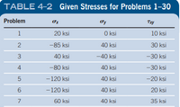
For the sets of given stresses on an element given in Table 4–2, draw a complete Mohr’s circle, find the principal stresses and the maximum shear stress, and draw the principal stress element and the maximum shear stress element. Any stress components not shown are assumed to be zero.
Work problem #4
4) Sigma_X= -80 ksi, Signma_Y= 40 ksi, Tau_XY= -30 ksi

Transcribed Image Text:TABLE 4-2 Given Stresses for Problems 1-30
Problem
Ty
Txy
1
20 ksi
O ksi
10 ksi
2
-85 ksi
40 ksi
30 ksi
3
40 ksi
-40 ksi
-30 ksi
4
-80 ksi
40 ksi
-30 ksi
-120 ksi
40 ksi
-20 ksi
-120 ksi
40 ksi
20 ksi
7
60 ksi
40 ksi
35 ksi
Expert Solution
This question has been solved!
Explore an expertly crafted, step-by-step solution for a thorough understanding of key concepts.
Step by stepSolved in 4 steps with 3 images

Knowledge Booster
Learn more about
Need a deep-dive on the concept behind this application? Look no further. Learn more about this topic, mechanical-engineering and related others by exploring similar questions and additional content below.Similar questions
- For the plane stress state shown: (a) Determine the principal stresses and show them on a properly oriented element. For this part, use the transformation equations only and not Mohr's circle. (b) Repeat part (a) using Mohr's circle. (c) Determine the maximum shear stress and show the complete state of stress on a properly oriented element containing this maximum shear stress. 25 kpsi 15 kpsi 12 kpsi Xarrow_forwardPlz solve correctlyarrow_forwardCorrect ans is 40,30 option barrow_forward
- Find the interal normal stress in all relevant segments of the bar in the picture.arrow_forwardPlease show full work than youarrow_forward2. The figure below shows a shaft with pulley and gear. Find the location along the x axis where the normal and shear stresses are the greatest. Create an element drawing of the stress state at this location. Find the principal stresses. Hints:1. the shaft diameter is not given, but you can find the stresses as a function of diameter. 2. Because the shaft is rotating, the maximum normal stress can be determined by using the resultant moment. 1. 622 YA ΤΑ 6 in. - 4 in. Gear/ 600 lb 2000 lb 79 Fp=? 12 in. 200 lb 1 +3 in.-102 D 8 in. Pulley B Xarrow_forward
- For each of the plane stress states listed below, draw a Mohr's circle diagram properly labeled, find the principal normal and shear stresses, and determine the angle from the r axis to of. Draw stress elements as in Figure 3-11c and d and label all details. a.) sigma,x = - 12 kpsi, sigma,y = 22 kpsi, txy = 12 kpsi cw b.) sigma,x = 30 kpsi, sigma,y = -10 kpsi, txy = 10 kpsi ccw c.) sigma,x = -10 kpsi, sigma,y = 18 kpsi, txy = 9 kpsi cw Attached is an image of Figure 3-11c and d for example. THIS IS THE ONLY INFORMATION I AM PROVIDED WITH! Thank you for the help in advance!arrow_forwardFor the plane stress sigma x = -8MPa, sigma y = 7MPa, tow xy= 6MPa cw, draw a Mohr’s circle diagram properly labeled, find the principal normal and shear stresses, and determine the angle from the axis to . Draw stress elementsarrow_forwardSuppose that σ = 330 psi and Try = 150 psi in (Figure 1). Figure Part D Specify the orientation of the principal stress. Take the positive direction of rotation counterclockwise. Express your answer in degrees to three significant figures. Op₁= Part E OF 0₂ = ΑΣΦΙΚΗ vec Specify the orientation of the maximum in-plane shear stress. Take the positive direction of rotation counterclockwise. Express your answer in degrees to three significant figures. 0/ —| ΑΣΦ 11 | vec ? ? oarrow_forward
- Consider the 2-D state of stress shown below. Using the provided scales graph the Mohr's Circle for the 2-D state of stress with “full" details II-Obtain the Principal Stresses, the Maximum Shear Stress, and complete the table below III- Draw the Planes of Principal and Maximum Shear Stresses in the space provided below Provide "full" details and Use 3 Sig. Fig. in this problem Oy = 15 Ksi Tcw > S y Ox =10 Ksi Тух 5 Ksi 10 5 -20 -15 -10 5 10 15 20 5 10 Tccw > S' O Avg. TMax. 01 02 Op1arrow_forwardAll of the parts, please. Thanks!arrow_forwardShow step-by-step solution and schematic diagram if possible.arrow_forward
arrow_back_ios
SEE MORE QUESTIONS
arrow_forward_ios
Recommended textbooks for you
 Elements Of ElectromagneticsMechanical EngineeringISBN:9780190698614Author:Sadiku, Matthew N. O.Publisher:Oxford University Press
 Mechanics of Materials (10th Edition)Mechanical EngineeringISBN:9780134319650Author:Russell C. HibbelerPublisher:PEARSON
 Thermodynamics: An Engineering ApproachMechanical EngineeringISBN:9781259822674Author:Yunus A. Cengel Dr., Michael A. BolesPublisher:McGraw-Hill Education
 Control Systems EngineeringMechanical EngineeringISBN:9781118170519Author:Norman S. NisePublisher:WILEY
 Mechanics of Materials (MindTap Course List)Mechanical EngineeringISBN:9781337093347Author:Barry J. Goodno, James M. GerePublisher:Cengage Learning
 Engineering Mechanics: StaticsMechanical EngineeringISBN:9781118807330Author:James L. Meriam, L. G. Kraige, J. N. BoltonPublisher:WILEY

Elements Of Electromagnetics
Mechanical Engineering
ISBN:9780190698614
Author:Sadiku, Matthew N. O.
Publisher:Oxford University Press

Mechanics of Materials (10th Edition)
Mechanical Engineering
ISBN:9780134319650
Author:Russell C. Hibbeler
Publisher:PEARSON

Thermodynamics: An Engineering Approach
Mechanical Engineering
ISBN:9781259822674
Author:Yunus A. Cengel Dr., Michael A. Boles
Publisher:McGraw-Hill Education

Control Systems Engineering
Mechanical Engineering
ISBN:9781118170519
Author:Norman S. Nise
Publisher:WILEY

Mechanics of Materials (MindTap Course List)
Mechanical Engineering
ISBN:9781337093347
Author:Barry J. Goodno, James M. Gere
Publisher:Cengage Learning

Engineering Mechanics: Statics
Mechanical Engineering
ISBN:9781118807330
Author:James L. Meriam, L. G. Kraige, J. N. Bolton
Publisher:WILEY