Introductory Circuit Analysis (13th Edition)
13th Edition
ISBN: 9780133923605
Author: Robert L. Boylestad
Publisher: PEARSON
expand_more
expand_more
format_list_bulleted
Concept explainers
Question
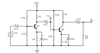
3.For the Silicon transistors of the circuit of figure 3, β = 110 and the Early Voltage is equal to infinity
a) Determine the value of the gain Av = vo/vs2
Note: It is known that Vcc = 25v.

Transcribed Image Text:Cc1
Vs2
80k
20k
VCC
1k
2k
Q3
Vol
HE
Cc2
Cel
15k
85k
Q4
4k
0.5k
Cc3
HE
Ce2
RL
4k
Vo
Expert Solution
arrow_forward
Step 1
We need to find out the overall gain for given circuit , first we will find the small signal parameters by using of DC analysis then we will find the gain by using of small signal model .
Step by stepSolved in 3 steps with 2 images

Knowledge Booster
Learn more about
Need a deep-dive on the concept behind this application? Look no further. Learn more about this topic, electrical-engineering and related others by exploring similar questions and additional content below.Similar questions
- 1) For circuit given in Figure below, calculate the Iz and Vz for two sets of V; voltage values given below. (Vz= 6.2 v) 2) Plot zener diode characteristic using the values calculated in Part 1 (add image of your hand-drawn) and give your comments V; = 0 V, 0.3 V, 0.6 V, 0.8 V, 0.9 V, 1 V V; = -1V, -3V, -6 V, -8 V, -10 V 200 0 V,arrow_forwardDraw the n-p-n silicon bipolar junction transistor at zero bias and also in forward active mode with an aid of the energy band diagram. Please ensure to draw with careful detail, reflecting the doping density in each region.arrow_forwardPlease explain briefly and show your complete solution. Thanks!!arrow_forward
- ) Draw the Forward and reverse bias PN junction diagram using the following voltages (10V, -9V) and (-5V, OV) respectively (i1) Explain the operation of the above circuits.arrow_forwardDesign a voltage-divider bias network using a supply of 24 V, a transistor with a beta of 100, VBE = 0.7 V ,and an operating point of ICQ = 4 mA and VCEQ = 8 V, R1 = 6R2. Choose VE =1/8 VCC.arrow_forwardA base bias method is used in the following circuit. For Bpc - 300, the value of emitter current is: -Vc. +15 V Rc 1.8 k2 RB 560 k2 7.82 mA O 6.84 mA O 7.27 mAarrow_forward
- 1. The drain current for the E-MOSFET shown in the following figure is 3.0 mA. What type of bias i this? a. Can a JFET use this type of bias? b. Compute the value of VD. c. Compute the value of VG- RG www 10 ΜΩ +VDD +15 V www RD · 2.7 ΚΩ =Iarrow_forwardQ1: for a silicon transistor in the figure below = 200 dc {What is the voltage between the collector and emitter VCE, drawing the load line and finding the Q pointarrow_forward3. If the Zener diode in the circuit below has a FBV of 1V, plot the transfer function (Vout vs. Vin) for -20Varrow_forwardThe operating point of the npn transistor is defined by a couple of values: Icand Ver- Select one: OTrue O False In the following figure. Q, and Q: are identicaland operate in active mode. if la =9 Icz then V,V2 ICarrow_forwardThe rate of fall of current in a diode with reverse recovery charge and reverse recovery current of 59 µC and 37.5 A respectively is_______________________ A/µs .arrow_forwardIn the circuit shown in the figure, the internal resistance of a voltage source is given as 3 ohms. Load values are such that R = 20 ohms and X = 20 ohms. The effective value of the VAB voltage at the load ends is 220 V. (Frequency is 50 Hz). What is the active power consumed by the load? (Do not take into account 3 ohms in calculations)arrow_forwardarrow_back_iosSEE MORE QUESTIONSarrow_forward_ios
Recommended textbooks for you
 Introductory Circuit Analysis (13th Edition)Electrical EngineeringISBN:9780133923605Author:Robert L. BoylestadPublisher:PEARSON
 Delmar's Standard Textbook Of ElectricityElectrical EngineeringISBN:9781337900348Author:Stephen L. HermanPublisher:Cengage Learning
 Programmable Logic ControllersElectrical EngineeringISBN:9780073373843Author:Frank D. PetruzellaPublisher:McGraw-Hill Education
 Fundamentals of Electric CircuitsElectrical EngineeringISBN:9780078028229Author:Charles K Alexander, Matthew SadikuPublisher:McGraw-Hill Education
 Electric Circuits. (11th Edition)Electrical EngineeringISBN:9780134746968Author:James W. Nilsson, Susan RiedelPublisher:PEARSON
 Engineering ElectromagneticsElectrical EngineeringISBN:9780078028151Author:Hayt, William H. (william Hart), Jr, BUCK, John A.Publisher:Mcgraw-hill Education,

Introductory Circuit Analysis (13th Edition)
Electrical Engineering
ISBN:9780133923605
Author:Robert L. Boylestad
Publisher:PEARSON

Delmar's Standard Textbook Of Electricity
Electrical Engineering
ISBN:9781337900348
Author:Stephen L. Herman
Publisher:Cengage Learning

Programmable Logic Controllers
Electrical Engineering
ISBN:9780073373843
Author:Frank D. Petruzella
Publisher:McGraw-Hill Education

Fundamentals of Electric Circuits
Electrical Engineering
ISBN:9780078028229
Author:Charles K Alexander, Matthew Sadiku
Publisher:McGraw-Hill Education

Electric Circuits. (11th Edition)
Electrical Engineering
ISBN:9780134746968
Author:James W. Nilsson, Susan Riedel
Publisher:PEARSON

Engineering Electromagnetics
Electrical Engineering
ISBN:9780078028151
Author:Hayt, William H. (william Hart), Jr, BUCK, John A.
Publisher:Mcgraw-hill Education,