Elements Of Electromagnetics
7th Edition
ISBN: 9780190698614
Author: Sadiku, Matthew N. O.
Publisher: Oxford University Press
expand_more
expand_more
format_list_bulleted
Question

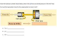
Transcribed Image Text:**Hydraulic Cylinder Analysis**
Given the hydraulic cylinder shown below, determine the following:
(a) What is the force out (\( F_{\text{out}} \))?
(b) What is the pressure (\( p \)) in the line?
(c) How far (\( D_{\text{in}} \)) must the input piston move for the output piston to move 1 inch?
**Diagram Explanation:**
- **Force In:** The system inputs 10 lbs of force.
- **Piston Areas:**
- **Input Piston Area:** 1 in²
- **Output Piston Area:** 10 in²
**Flow of Force:**
- The force is applied to the input piston with an area of 1 in².
- The force is transferred through the hydraulic fluid to the output piston.
- The increase in piston area from 1 in² to 10 in² affects the output force.
**Equations/Empty Fields:**
- a. \( F_{\text{out}} = \) ____________
- b. \( p = \) ____________
- c. \( D_{\text{in}} = \) ____________
The illustration highlights the input and output sections with arrows and labels indicating the direction of force application. The areas of the pistons are clearly marked to demonstrate how force and movement relate across the system.
Expert Solution
arrow_forward
Step 1
Given data,
Force in , F1= 10 lbs
A1= 1 in2
A2=10 in2
Step by stepSolved in 2 steps

Knowledge Booster
Similar questions
- Please solve the question on the sheet and get a clear picture and submit the picture. thankyouarrow_forwardA submarine robot explorer is used to explore the marine life in deep water. The weakest point in the submarine robot explorer structure can hold a pressure force of 300 MPa. What is the deepest point can it reach? *arrow_forwardPlease help. Written on paper not typed on computer or keyboard please. Need help on all questions. Please include all units, steps to the problem and information such as its direction or if it is in compression or tension. Thx.arrow_forward
- B1arrow_forwardNote: Please deliver a clear, step-by-step handwritten calculation (without any explanations!), ensuring it is created without any AI assistance. I expect a top-quality, expert-level handwritten solution, and I will evaluate and rate it based on its accuracy and precision. Double-check every detail for correctness before submission. Appreciate your time and effort!. Question is down below: In Figure 3, when y = 160 mm, the piston rod of the hydraulic cylinder C imparts a vertical motion to the pin B consisting of y = 400 mm/s and ÿ = -100 mm/s'. For this instant determine the angular velocity w and the angular acceleration a of link OA. Members OA and AB make equal angles with the horizontal at this instant.arrow_forwardThe final answer must be correct otherwise leave . Don't provide wrong answer ,It will be downvoted.arrow_forward
- Pleis solve the 2 parts of the questyon! it is connected so it is needed to be solve together, be considerate and make sure it is correct, if not this will be downvote...!!! part a&b help please you are good if helpingarrow_forwardTrue Story! The 1998-1999 Mars Climate Orbiter mission was declared a total loss in1999 as there was a unit conversion mismatch error between Lockheed Martin and NASA. Themismatch was in the thruster force units. NASA used the SI system which called forNewton-Seconds (4.45 times as large) of thrust and Lockheed Martin used Pound-Force Seconds.Calculations placed the Orbiter at 68 miles from the surface as it went into orbit, but it waswithin 57 km of the surface after the breaking maneuver. Any distance from the surface lessthan 50 miles would have caused the Orbiter to crash.a. What was the actual distance of the Orbiter from the surface in miles?b. In percentage, how far off from the calculated 68 miles was the Orbiter?arrow_forwardPLEASE ANSWER THEM ALL FOR AN UPVOTE. THANK YOU. Given: Pi constant to be used: 3.14159 Capillary tube: radius = 0.02 cm; length = 9 cm; pressure = 0.7 mmHg Liquid sample: density = 4 ml; time of flow = 4.5 seconds Ans. the ff questions. •What is the pressure in MKS unit? •What is the pressure in CGS unit? •What is the viscosity of the liquid? • If the weight was given as 8.5 grams, what will be the density of the liquid? •What is the kinematic viscosity of the liquid? •What is the fluidity of the liquid?arrow_forward
- 1. Need help, round answers to 3 sig figs pleasearrow_forwardHello pls write this on white page ASAP just copy this whole on white page I'll UPVOTEarrow_forwardfollow the steps while answering step by step detailed answer good HANDWRINTING (DONT REJECT LET OTHER ANSWER THE QUESTION IF YOU DONT HAVE IDEA )arrow_forward
arrow_back_ios
SEE MORE QUESTIONS
arrow_forward_ios
Recommended textbooks for you
 Elements Of ElectromagneticsMechanical EngineeringISBN:9780190698614Author:Sadiku, Matthew N. O.Publisher:Oxford University Press
 Mechanics of Materials (10th Edition)Mechanical EngineeringISBN:9780134319650Author:Russell C. HibbelerPublisher:PEARSON
 Thermodynamics: An Engineering ApproachMechanical EngineeringISBN:9781259822674Author:Yunus A. Cengel Dr., Michael A. BolesPublisher:McGraw-Hill Education
 Control Systems EngineeringMechanical EngineeringISBN:9781118170519Author:Norman S. NisePublisher:WILEY
 Mechanics of Materials (MindTap Course List)Mechanical EngineeringISBN:9781337093347Author:Barry J. Goodno, James M. GerePublisher:Cengage Learning
 Engineering Mechanics: StaticsMechanical EngineeringISBN:9781118807330Author:James L. Meriam, L. G. Kraige, J. N. BoltonPublisher:WILEY

Elements Of Electromagnetics
Mechanical Engineering
ISBN:9780190698614
Author:Sadiku, Matthew N. O.
Publisher:Oxford University Press

Mechanics of Materials (10th Edition)
Mechanical Engineering
ISBN:9780134319650
Author:Russell C. Hibbeler
Publisher:PEARSON

Thermodynamics: An Engineering Approach
Mechanical Engineering
ISBN:9781259822674
Author:Yunus A. Cengel Dr., Michael A. Boles
Publisher:McGraw-Hill Education

Control Systems Engineering
Mechanical Engineering
ISBN:9781118170519
Author:Norman S. Nise
Publisher:WILEY

Mechanics of Materials (MindTap Course List)
Mechanical Engineering
ISBN:9781337093347
Author:Barry J. Goodno, James M. Gere
Publisher:Cengage Learning

Engineering Mechanics: Statics
Mechanical Engineering
ISBN:9781118807330
Author:James L. Meriam, L. G. Kraige, J. N. Bolton
Publisher:WILEY