
Introductory Circuit Analysis (13th Edition)
13th Edition
ISBN: 9780133923605
Author: Robert L. Boylestad
Publisher: PEARSON
expand_more
expand_more
format_list_bulleted
Related questions
Question

Transcribed Image Text:+
17:
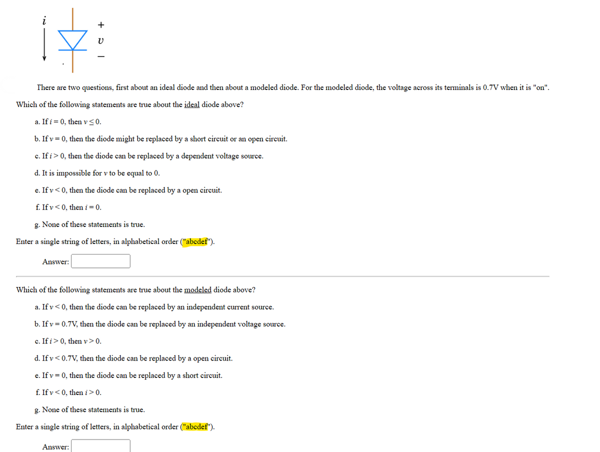
There are two questions, first about an ideal diode and then about a modeled diode. For the modeled diode, the voltage across its terminals is 0.7V when it is "on".
Which of the following statements are true about the ideal diode above?
a. If i = 0, then v ≤ 0.
b. If v = 0, then the diode might be replaced by a short circuit or an open circuit.
c. If i > 0, then the diode can be replaced by a dependent voltage source.
d. It is impossible for v to be equal to 0.
e. If v<0, then the diode can be replaced by a open circuit.
f. If v<0, then i = 0.
g. None of these statements is true.
Enter a single string of letters, in alphabetical order ("abcdef").
Answer:
Which of the following statements are true about the modeled diode above?
a. If v<0, then the diode can be replaced by an independent current source.
b. If v = 0.7V, then the diode can be replaced by an independent voltage source.
c. If i > 0, then v > 0.
d. If v < 0.7V, then the diode can be replaced by a open circuit.
e. If v = 0, then the diode can be replaced by a short circuit.
f. If v<0, then i > 0.
g. None of these statements is true.
Enter a single string of letters, in alphabetical order ("abcdef").
Answer:

Transcribed Image Text:A diode is a two-terminal, electronic device made using semiconductors that is designed to prevent current from flowing in a particular direction. The symbol is a triangle pointing in the direction that (positive) current is allowed to flow and a wall preventing (positive) current from flowing in the opposite direction:
1:
A diode has two modes, "on" and "off". When "on", current flows, and when "off", no current flows. We generally view diodes as either "ideal" or "modeled", as described below.
"Ideal" view of a diode
+
The "ideal" diode is either a short circuit or an open circuit. Specifically, when the voltage across its terminals is negative, no current flows, and when current flows, there is zero voltage across its terminals, as pictured below:
Diode
"Modeled" view of a diode
+51
Diode
V
Ideal Diode "Off"
i=0|
+
U≤0
+
I
Therefore, with current i and voltage v defined as shown on the left above, for an "ideal" diode:
• Current i cannot be negative.
Voltage v cannot be positive.
. The diode cannot absorb or deliver power.
NOTE: The first two statements will change if the current arrow and/or voltage polarity change.
Ideal Diode "On"
i> 0
For a more realistic view of a diode, we replace the short when "on" with a small independent voltage source. When (positive) current is flowing in the direction of the triangle, the diode behaves like a 0.7V source. (Other values of the voltage are possible, but 0.7V is a particularly common value.) When the voltage is less than 0.7V, the diode is "off" and no current flows, as pictured below:
Modeled Diode "Off"
+
v=0
Modeled Diode "On"
i=0|
+
IZETTE
V < 0.7V
i> 0
+
V = 0.7V
Therefore, again with current i and voltage v defined as shown on the left above, for a "modeled" diode:
• Current i cannot be negative.
• Voltage v cannot be greater than 0.7V. (It can be negative.)
• When "off", the modeled diode absorbs no power. When "on", the modeled diode necessarily absorbs positive power.
NOTE: The first two statements will change if the current arrow and/or voltage polarity change.
Expert Solution
This question has been solved!
Explore an expertly crafted, step-by-step solution for a thorough understanding of key concepts.

Step by stepSolved in 3 steps with 3 images

Knowledge Booster


Learn more about
Need a deep-dive on the concept behind this application? Look no further. Learn more about this topic, electrical-engineering and related others by exploring similar questions and additional content below.Similar questions
- Please show all work, thank you :)arrow_forwardFor the diode circuit to the right 8002 a V 1002 b 40mA 0.001V' a) To the left of points a and b, find the load-line relation by expressing the current, I with voltage, V. HINT: Write KCL equation for the circuit diagram and write I in terms of V from that KCL equation. This will be your load-line equation. b) Assume the diode has the following characteristic, using the load-line relation you found in (a), determine the operating voltage, V and current, I for the circuit. ip (mA) 20 15 10 5 Vp (V) 3.0 0.5 '1.0 1.5 2.0 2.5arrow_forwardVi (t) = 10.sinwt Does not pass positive alternans when Volt input voltage is applied, only Design and explain two different circuits that pass negative alternans. Draw the input and output voltages. What are the types of these circuits? (Note: You can use the ideal diode approach)arrow_forward
- After solving a circuit with ideal diodes (Vf=0), what check is necessary for diodes initially assumed to be on? Off? We must check to see that reverse voltage appears across all diodes assumed to be on, and we must check to see that forward current flows in diodes assumed to be off We must check to see that forward current flows in diodes assumed to be on, and we must check to see that reverse voltage appears across all diodes assumed to be offarrow_forwardFrom the diode circuit shown below, If E=30 V and RL=802, determine the current supplied from the battery, the voltage across the load resistance, and the voltage across diode D2 if all the diodes are silicon with an internal resistance of 1 2. D . RL D4 D3 a. The Current supplied by battery is b. The Voltage across Load resistance RL is c. The Voltage across diode D2 isarrow_forward3. In the following circuits, given source voltage Vs=9V, R1, R2 and R3 all are 1kOhms. Answer the questions by considering the diodes as ideal and practical silicon ones respectively. Vs Vs Vs R2 R2 R2 Vout P D R1 R1 R3 R1 (a) Vout = ? (b) Vp = ? (c) Vp = ? Note: Vp means the voltage at point p. warrow_forward
arrow_back_ios
arrow_forward_ios
Recommended textbooks for you
- Introductory Circuit Analysis (13th Edition)Electrical EngineeringISBN:9780133923605Author:Robert L. BoylestadPublisher:PEARSON
 Delmar's Standard Textbook Of ElectricityElectrical EngineeringISBN:9781337900348Author:Stephen L. HermanPublisher:Cengage Learning
 Programmable Logic ControllersElectrical EngineeringISBN:9780073373843Author:Frank D. PetruzellaPublisher:McGraw-Hill Education
  Fundamentals of Electric CircuitsElectrical EngineeringISBN:9780078028229Author:Charles K Alexander, Matthew SadikuPublisher:McGraw-Hill Education
 Electric Circuits. (11th Edition)Electrical EngineeringISBN:9780134746968Author:James W. Nilsson, Susan RiedelPublisher:PEARSON
 Engineering ElectromagneticsElectrical EngineeringISBN:9780078028151Author:Hayt, William H. (william Hart), Jr, BUCK, John A.Publisher:Mcgraw-hill Education,
Introductory Circuit Analysis (13th Edition)
Electrical Engineering
ISBN:9780133923605
Author:Robert L. Boylestad
Publisher:PEARSON
Delmar's Standard Textbook Of Electricity
Electrical Engineering
ISBN:9781337900348
Author:Stephen L. Herman
Publisher:Cengage Learning
Programmable Logic Controllers
Electrical Engineering
ISBN:9780073373843
Author:Frank D. Petruzella
Publisher:McGraw-Hill Education
Fundamentals of Electric Circuits
Electrical Engineering
ISBN:9780078028229
Author:Charles K Alexander, Matthew Sadiku
Publisher:McGraw-Hill Education
Electric Circuits. (11th Edition)
Electrical Engineering
ISBN:9780134746968
Author:James W. Nilsson, Susan Riedel
Publisher:PEARSON
Engineering Electromagnetics
Electrical Engineering
ISBN:9780078028151
Author:Hayt, William H. (william Hart), Jr, BUCK, John A.
Publisher:Mcgraw-hill Education,