
Introductory Circuit Analysis (13th Edition)
13th Edition
ISBN: 9780133923605
Author: Robert L. Boylestad
Publisher: PEARSON
expand_more
expand_more
format_list_bulleted
Related questions
Concept explainers
Question
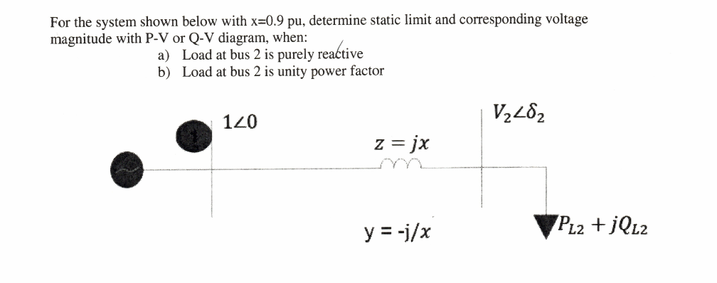

Transcribed Image Text:For the system shown below with x=0.9 pu, determine static limit and corresponding voltage
magnitude with P-V or Q-V diagram, when:
a) Load at bus 2 is purely reactive
b) Load at bus 2 is unity power factor
120
z = jx
y = -j/x
PL2 +JQL2
Expert Solution
This question has been solved!
Explore an expertly crafted, step-by-step solution for a thorough understanding of key concepts.

This is a popular solution

Trending nowThis is a popular solution!

Step by stepSolved in 5 steps with 3 images

Knowledge Booster


Learn more about
Need a deep-dive on the concept behind this application? Look no further. Learn more about this topic, electrical-engineering and related others by exploring similar questions and additional content below.Similar questions
- 5.5 kW, 1450 rpm. L-type equivalent circuit and parameters for a continuous sinusoidal phase of a star connected 3-phase ASM with line voltage 220 V and frequency 50 Hz are given as follows, ignoring core (iron) losses: R1=0.21 Ohm, R2=-0.18 Ohm, X1=X2-0.66 Ohm and Xm = 9.9 Ohm How many times the inrush current will be the rated current when the ASM is started directly? Answer options group 8.0815 2.6455 4.3763 7.1534 1.2558 6.3414 5.2280 3.7473arrow_forwardPlease answer in typing format please ASAP for the like please clear the solution of above question is given to the solution Please answer in typing format please ASAParrow_forwardd) A regulator as shown in Figure 4 has an input voltage, Vs 12 V. The duty cycle, k = 0.35 and the switching frequency is 30 kHz. It also has an inductance, L= 200 µH, filter capacitance, C = 440 µF. The average load current, la = 1.25 A. Determine the; i. average output voltage, Va. ii. peak-to-peak output ripple voltage, AVc. iii. peak-to-peak output ripple current of inductor, AI. iv. peak current of the transistor, Ip. v. critical values of L and C. vi. critical values of L and C if Vs is increased to 14 V. Estimate the change in percentage for the critical values of L and C. V, Load V V G Figure 4arrow_forward
arrow_back_ios
arrow_forward_ios
Recommended textbooks for you
- Introductory Circuit Analysis (13th Edition)Electrical EngineeringISBN:9780133923605Author:Robert L. BoylestadPublisher:PEARSON
 Delmar's Standard Textbook Of ElectricityElectrical EngineeringISBN:9781337900348Author:Stephen L. HermanPublisher:Cengage Learning
 Programmable Logic ControllersElectrical EngineeringISBN:9780073373843Author:Frank D. PetruzellaPublisher:McGraw-Hill Education
  Fundamentals of Electric CircuitsElectrical EngineeringISBN:9780078028229Author:Charles K Alexander, Matthew SadikuPublisher:McGraw-Hill Education
 Electric Circuits. (11th Edition)Electrical EngineeringISBN:9780134746968Author:James W. Nilsson, Susan RiedelPublisher:PEARSON
 Engineering ElectromagneticsElectrical EngineeringISBN:9780078028151Author:Hayt, William H. (william Hart), Jr, BUCK, John A.Publisher:Mcgraw-hill Education,
Introductory Circuit Analysis (13th Edition)
Electrical Engineering
ISBN:9780133923605
Author:Robert L. Boylestad
Publisher:PEARSON
Delmar's Standard Textbook Of Electricity
Electrical Engineering
ISBN:9781337900348
Author:Stephen L. Herman
Publisher:Cengage Learning
Programmable Logic Controllers
Electrical Engineering
ISBN:9780073373843
Author:Frank D. Petruzella
Publisher:McGraw-Hill Education
Fundamentals of Electric Circuits
Electrical Engineering
ISBN:9780078028229
Author:Charles K Alexander, Matthew Sadiku
Publisher:McGraw-Hill Education
Electric Circuits. (11th Edition)
Electrical Engineering
ISBN:9780134746968
Author:James W. Nilsson, Susan Riedel
Publisher:PEARSON
Engineering Electromagnetics
Electrical Engineering
ISBN:9780078028151
Author:Hayt, William H. (william Hart), Jr, BUCK, John A.
Publisher:Mcgraw-hill Education,