
Introductory Circuit Analysis (13th Edition)
13th Edition
ISBN: 9780133923605
Author: Robert L. Boylestad
Publisher: PEARSON
expand_more
expand_more
format_list_bulleted
Related questions
Concept explainers
Question
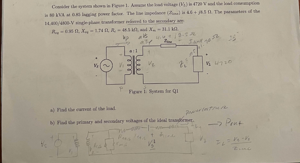

Transcribed Image Text:Consider the system shown in Figure 1. Assume the load voltage (VL) is 4720 V and the load consumption
is 80 kVA at 0.85 lagging power factor. The line impedance (Zline) is 4.6+j8.5 2. The parameters of the
14,400/4800-V single-phase transformer referred to the secondary are:
Req=0.95 , Xeq = 1.74 , Re = 48.5 kn, and Xm = 31.1 k.
vp
avs
4.6 +19.52
Zline
Vs ~
P
a:1
ele
rmis
alf
Reais
leee
V₂
zí
S
Figure 1: System for Q1
I wad
a) Find the current of the load.
b) Find the primary and secondary voltages of the ideal transformer.
nuomo I un cucc
+ Bline
Xeq,s
1
V₂²
95,
74-32
1.
VL 4720
Ponerlosture
-> Pont
IL
= V₂ -V₂
Zine
Expert Solution
This question has been solved!
Explore an expertly crafted, step-by-step solution for a thorough understanding of key concepts.

This is a popular solution

Trending nowThis is a popular solution!

Step by stepSolved in 4 steps with 6 images

Knowledge Booster


Learn more about
Need a deep-dive on the concept behind this application? Look no further. Learn more about this topic, electrical-engineering and related others by exploring similar questions and additional content below.Similar questions
- 2. Given three identical ideal single-phase transformers with each rated at 100KVA and 7kV/3.5kV, they are connected as a three-phase transformer bank. The three-phase transformer has high voltage side connected in delta and the low voltage side is connected in wye. A three-phase 200KVA, wye connected load is connected at the low voltage side of the transformer. Calculate the following: a. Rated line-to-line voltage on each side b. Line current on each side of the transformerarrow_forwardA short transmission line connects a step-up transformer on the source side with a series impedance of j0.5 ohms (referred to the primary) to a step-down transformer on the load side with a series impedance of 50 ohms (referred to the primary). The turn ratio of the step-up transformer is 1:10 and a no-load primary voltage of 13.2 (line-to-line) kV. The step-down transformer has a turn ratio of 15:1 and it has a Y-connected, balanced load of 0.667 +j 0.111 ohms connected to its secondary side. A capacitor bank of -j0.239 ohms is added parallel to the load. Assuming an ideal transmission line, the load voltage (line-to-neutral) would be: A. 5118 V B. 6.2 kV C. 8865 V D. None of the other choices are correct E. 4225 Varrow_forward
Recommended textbooks for you
- Introductory Circuit Analysis (13th Edition)Electrical EngineeringISBN:9780133923605Author:Robert L. BoylestadPublisher:PEARSON
 Delmar's Standard Textbook Of ElectricityElectrical EngineeringISBN:9781337900348Author:Stephen L. HermanPublisher:Cengage Learning
 Programmable Logic ControllersElectrical EngineeringISBN:9780073373843Author:Frank D. PetruzellaPublisher:McGraw-Hill Education
  Fundamentals of Electric CircuitsElectrical EngineeringISBN:9780078028229Author:Charles K Alexander, Matthew SadikuPublisher:McGraw-Hill Education
 Electric Circuits. (11th Edition)Electrical EngineeringISBN:9780134746968Author:James W. Nilsson, Susan RiedelPublisher:PEARSON
 Engineering ElectromagneticsElectrical EngineeringISBN:9780078028151Author:Hayt, William H. (william Hart), Jr, BUCK, John A.Publisher:Mcgraw-hill Education,
Introductory Circuit Analysis (13th Edition)
Electrical Engineering
ISBN:9780133923605
Author:Robert L. Boylestad
Publisher:PEARSON
Delmar's Standard Textbook Of Electricity
Electrical Engineering
ISBN:9781337900348
Author:Stephen L. Herman
Publisher:Cengage Learning
Programmable Logic Controllers
Electrical Engineering
ISBN:9780073373843
Author:Frank D. Petruzella
Publisher:McGraw-Hill Education
Fundamentals of Electric Circuits
Electrical Engineering
ISBN:9780078028229
Author:Charles K Alexander, Matthew Sadiku
Publisher:McGraw-Hill Education
Electric Circuits. (11th Edition)
Electrical Engineering
ISBN:9780134746968
Author:James W. Nilsson, Susan Riedel
Publisher:PEARSON
Engineering Electromagnetics
Electrical Engineering
ISBN:9780078028151
Author:Hayt, William H. (william Hart), Jr, BUCK, John A.
Publisher:Mcgraw-hill Education,