
Introductory Circuit Analysis (13th Edition)
13th Edition
ISBN: 9780133923605
Author: Robert L. Boylestad
Publisher: PEARSON
expand_more
expand_more
format_list_bulleted
Related questions
Concept explainers
Question

Transcribed Image Text:**Determining Input Resistance Using Thevenin Analysis**
**Objective:**
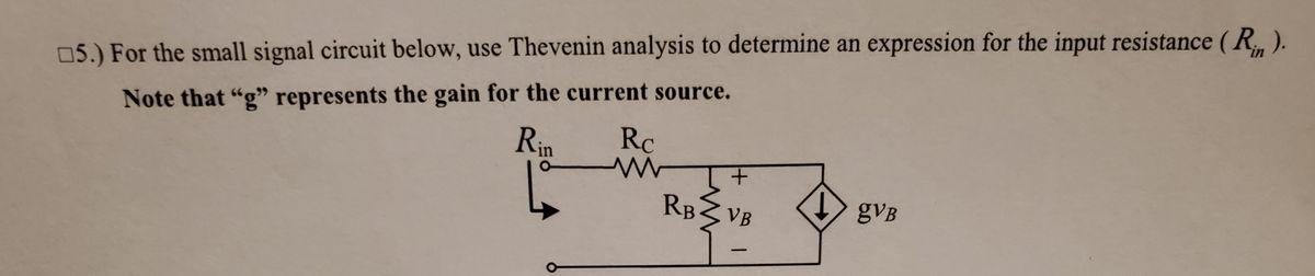
For the small signal circuit shown, use Thevenin analysis to determine an expression for the input resistance (\(R_{in}\)).
**Key Note:**
- The variable “g” represents the gain for the current source.
**Circuit Description:**
- The circuit includes:
- A resistor labeled \(R_{in}\), connected at the input.
- A resistor \(R_C\) in series with a branch containing a parallel combination of:
- A resistor \(R_B\)
- A voltage source \(v_B\)
- A dependent current source represented as \(g v_B\), connected in series with the parallel combination, where \(g\) is the gain factor.
**Instructions:**
Thevenin analysis is used to simplify a complex circuit into a simple equivalent circuit with a single voltage source and series resistance. In this context, it will help derive the expression for \(R_{in}\).
To carry out Thevenin analysis:
1. **Identify the portion of the circuit to be analyzed** for finding \(R_{in}\).
2. **Remove the load** from the output if present.
3. **Determine the open-circuit voltage (Thevenin voltage)** at the terminals of interest.
4. **Find the equivalent resistance (Thevenin resistance)** by deactivating all independent sources and calculating the resistance between the terminals.
By following these steps, you will deduce the expression for \(R_{in}\) in terms of the given components and the gain \(g\).
Expert Solution
This question has been solved!
Explore an expertly crafted, step-by-step solution for a thorough understanding of key concepts.

This is a popular solution

Trending nowThis is a popular solution!

Step by stepSolved in 2 steps with 2 images

Knowledge Booster


Learn more about
Need a deep-dive on the concept behind this application? Look no further. Learn more about this topic, electrical-engineering and related others by exploring similar questions and additional content below.Similar questions
- Five different CMo differential amplifier circuits are shown below. Use intuitive approach of finding the small signal current caused by the application of a small signal input voltage Vin, and write by inspection the approximate small signal output resistance, Rout, seen looking back into each amplifier and the approximate small signal differential voltage gain, vout/Vin. Leave your answer in terms of gmi and gasi (i=1 thru' 8) M. M, M. M, M. M. V BP V. aut auf M, M, M, V. M V. Vout M2 M2 V. (), II IV м. M. M, VEN M. Varrow_forwardFigure 4 shows a differential amplifier where the input voltage is Vin = Vil the output voltage is Vout - Vi2 and %3D Vo- (a) What kind of amplifier is it? Draw the small equivalent circuit and calculate the differential voltage gain G, in the case of balanced input and unbalanced output. For the calculation, consider the output resistances roi of the two transistors as open circuits (negligible current flowing in them). Show the detail of the calculation and state any assumption. (b) (c) What is Gv if you include the output resistances roi in the analysis? For the balanced input and identical transistors, the current variation in M1 and M2 are equal and opposite: i1 = -i2 (the current flowing in Rs is i- 0). V DD Rp1 Rp2 VinLM, M2 V2 V'ss =0 V Figure 4arrow_forwardWhat is coupled magnitudes? What is the significance of this difference in the coupled magnitudes to the lay-out of circuit fast signals?arrow_forward
- Hand Calculation: Since you now have the values of R1 and R2 resistors, obtain numeric value of voltage gain Av=Vo/Vi, and numerical values of input and output resistances Ri and Ro. Note that you need to DC analysis first. Do a hand calculation and calculate the DC collector current or IC. This is needed in order to calculate the small signal parameters gm and rπ and in turn to obtain the Av , Ri and Ro Hence, first perform a DC analysis (use the circuit in Figure 1 and take all capacitors open) and assume your transistor has a β=140.arrow_forwardAn operational amplifier consisting of three cascaded stages has a voltage gain of 3500. The gain of the first two stages is known to be -5 and -900. What is the voltage gain of the last stage and which type of MOSFET amplifier would you prefer for this stage?arrow_forwardFigure 6 shows a circuit where feedback is provided between the drain and gate of the transistor M1 Q6 Draw the small signal equivalent circuit of the open loop circuit obtained by breaking the loop at the gate of transistor M1 (suitable for the analysis in the mid band frequency range). Consider Cg as short circuit in the model and state any assumption. (a) (b) State the necessary conditions for the oscillation to occur in the circuit. Using the conditions from (b), derive an expression for the amplifier oscillation frequency fo. (c) Derive the necessary condition for the oscillation to occur in the circuit and state if you can conclude that the circuit will oscillate when considering the values of the inductances L2 = 8 LI = 2 mH; capacitors C = 2 nF; transconductance of the transistor gml = 1.4 mS; and resistors R1 = R2 = Rs : 10 k2. (d) %3D L2 L, R, Cg. C Vout Cp M1 R2 CG Rs Cs Vss = 0 V Figure 6arrow_forward
arrow_back_ios
arrow_forward_ios
Recommended textbooks for you
- Introductory Circuit Analysis (13th Edition)Electrical EngineeringISBN:9780133923605Author:Robert L. BoylestadPublisher:PEARSON
 Delmar's Standard Textbook Of ElectricityElectrical EngineeringISBN:9781337900348Author:Stephen L. HermanPublisher:Cengage Learning
 Programmable Logic ControllersElectrical EngineeringISBN:9780073373843Author:Frank D. PetruzellaPublisher:McGraw-Hill Education
  Fundamentals of Electric CircuitsElectrical EngineeringISBN:9780078028229Author:Charles K Alexander, Matthew SadikuPublisher:McGraw-Hill Education
 Electric Circuits. (11th Edition)Electrical EngineeringISBN:9780134746968Author:James W. Nilsson, Susan RiedelPublisher:PEARSON
 Engineering ElectromagneticsElectrical EngineeringISBN:9780078028151Author:Hayt, William H. (william Hart), Jr, BUCK, John A.Publisher:Mcgraw-hill Education,
Introductory Circuit Analysis (13th Edition)
Electrical Engineering
ISBN:9780133923605
Author:Robert L. Boylestad
Publisher:PEARSON
Delmar's Standard Textbook Of Electricity
Electrical Engineering
ISBN:9781337900348
Author:Stephen L. Herman
Publisher:Cengage Learning
Programmable Logic Controllers
Electrical Engineering
ISBN:9780073373843
Author:Frank D. Petruzella
Publisher:McGraw-Hill Education
Fundamentals of Electric Circuits
Electrical Engineering
ISBN:9780078028229
Author:Charles K Alexander, Matthew Sadiku
Publisher:McGraw-Hill Education
Electric Circuits. (11th Edition)
Electrical Engineering
ISBN:9780134746968
Author:James W. Nilsson, Susan Riedel
Publisher:PEARSON
Engineering Electromagnetics
Electrical Engineering
ISBN:9780078028151
Author:Hayt, William H. (william Hart), Jr, BUCK, John A.
Publisher:Mcgraw-hill Education,