
Introductory Circuit Analysis (13th Edition)
13th Edition
ISBN: 9780133923605
Author: Robert L. Boylestad
Publisher: PEARSON
expand_more
expand_more
format_list_bulleted
Related questions
Question
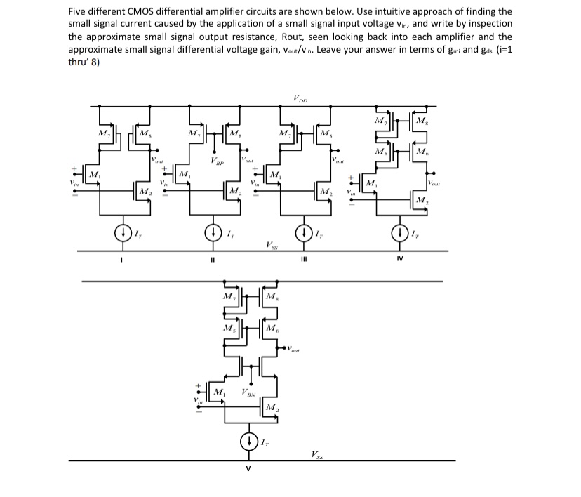

Transcribed Image Text:The image presents five different CMOS differential amplifier circuits labeled I through V. These circuits are used to investigate the small signal current caused by a small signal input voltage \(v_{in}\). The task is to determine the approximate small signal output resistance, \(R_{out}\), and the small signal differential voltage gain, \(v_{out}/v_{in}\), for each amplifier. The results should be expressed in terms of the transconductance \(g_{mi}\) and output conductance \(g_{dsi}\).
**Circuit Descriptions:**
1. **Circuit I:**
- Comprised of transistors \(M_1\), \(M_2\) connected to a current source \(I_T\). The output voltage is taken from the drains of \(M_1\) and \(M_2\).
2. **Circuit II:**
- Similar to Circuit I with an additional transistor \(M_3\) connected in a diode configuration, and a load represented by a transistor \(M_4\) providing a more complex response.
3. **Circuit III:**
- Incorporates a diode-connected load transistor \(M_3\) and a differential pair of transistors \(M_1\), \(M_2\) with the output taken across them.
4. **Circuit IV:**
- Uses transistors \(M_5\) and \(M_6\) as active loads with a differential configuration similar to Circuit III.
5. **Circuit V:**
- Features additional cascoding with transistors \(M_5\) and \(M_6\) added on top of the differential pair \(M_1\) and \(M_2\). Transistor \(M_7\) provides a biasing voltage \(V_{BN}\).
For each circuit, the input \(v_{in}\) is applied to the gates of the differential pair while the common-mode current source \(I_T\) provides biasing. The circuits are powered by \(V_{DD}\) as the positive supply rail and \(V_{SS}\) as the negative supply rail. The task involves understanding the intuition behind the circuit functions to estimate their gain and output resistance analytically.
Expert Solution
This question has been solved!
Explore an expertly crafted, step-by-step solution for a thorough understanding of key concepts.

Step by stepSolved in 2 steps

Knowledge Booster

Similar questions
arrow_back_ios
arrow_forward_ios
Recommended textbooks for you
- Introductory Circuit Analysis (13th Edition)Electrical EngineeringISBN:9780133923605Author:Robert L. BoylestadPublisher:PEARSON
 Delmar's Standard Textbook Of ElectricityElectrical EngineeringISBN:9781337900348Author:Stephen L. HermanPublisher:Cengage Learning
 Programmable Logic ControllersElectrical EngineeringISBN:9780073373843Author:Frank D. PetruzellaPublisher:McGraw-Hill Education
  Fundamentals of Electric CircuitsElectrical EngineeringISBN:9780078028229Author:Charles K Alexander, Matthew SadikuPublisher:McGraw-Hill Education
 Electric Circuits. (11th Edition)Electrical EngineeringISBN:9780134746968Author:James W. Nilsson, Susan RiedelPublisher:PEARSON
 Engineering ElectromagneticsElectrical EngineeringISBN:9780078028151Author:Hayt, William H. (william Hart), Jr, BUCK, John A.Publisher:Mcgraw-hill Education,
Introductory Circuit Analysis (13th Edition)
Electrical Engineering
ISBN:9780133923605
Author:Robert L. Boylestad
Publisher:PEARSON
Delmar's Standard Textbook Of Electricity
Electrical Engineering
ISBN:9781337900348
Author:Stephen L. Herman
Publisher:Cengage Learning
Programmable Logic Controllers
Electrical Engineering
ISBN:9780073373843
Author:Frank D. Petruzella
Publisher:McGraw-Hill Education
Fundamentals of Electric Circuits
Electrical Engineering
ISBN:9780078028229
Author:Charles K Alexander, Matthew Sadiku
Publisher:McGraw-Hill Education
Electric Circuits. (11th Edition)
Electrical Engineering
ISBN:9780134746968
Author:James W. Nilsson, Susan Riedel
Publisher:PEARSON
Engineering Electromagnetics
Electrical Engineering
ISBN:9780078028151
Author:Hayt, William H. (william Hart), Jr, BUCK, John A.
Publisher:Mcgraw-hill Education,