Introductory Circuit Analysis (13th Edition)
13th Edition
ISBN: 9780133923605
Author: Robert L. Boylestad
Publisher: PEARSON
expand_more
expand_more
format_list_bulleted
Question

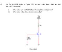
Transcribed Image Text:For the MOSFET shown in Figure Q2d, VGs (off) = -6V, IDss = 10.5 mA and
Vps = 11V. Determine,
d)
i)
What is the type of MOSFET and the amplifier configuration?
ii)
What is the value of the drain resistance, Rp?
15V
VDD
RD
Q1
LRG
9MO
Figure Q2d
Expert Solution
This question has been solved!
Explore an expertly crafted, step-by-step solution for a thorough understanding of key concepts.
Step by stepSolved in 4 steps with 2 images

Knowledge Booster
Learn more about
Need a deep-dive on the concept behind this application? Look no further. Learn more about this topic, electrical-engineering and related others by exploring similar questions and additional content below.Similar questions
- List the three distinct operation regions of a MOSFET and identify the region providing the highest gain. L2 Pg 2 produce a drain current of 10 mà from anarrow_forward(a) What is the output current IO in the circuitshown if −VEE = −10 V andR = 20 ohm? Assume that the MOSFET is saturated.(b) What is the minimum voltage VDDneeded to saturate the MOSFET if VTN = 2.5 Vand K'n = 0.25 A/V2. (c) What must be the powerdissipation ratings of resistor R and the FET.arrow_forwardi need the answer quicklyarrow_forward
- Determine in which mode (depletion, enhancement or neither) each D-MOSFET in the figure below.arrow_forwardd) In Figure 3.3 shows the circuit diagram of a typical n-channel JFET common source amplifier. If ac input impedance of this amplifier is RGG=1.XY MOhm, VG = 2.XYV, RD=1.5 x Rs and VDD = 15 V. Determine the value of Rs to set the Q-point to VGs = -0.5 V and ID=2.5 mA. What is the value of VDs at the Q-point? Sketch the amplifier's small signal equivalent circuit model. If the JFET transconductance at this bias point (Q-point) is gm=4.XY mS and go=0.1 ms, what is the AC open circuit voltage gain Av and the AC short circuit current gain Ai of this amplifier Vin RG1 Cin HH RG2 -41 VG + VDD RD Rs VD Cout www11 Figure 3.3 Vout Cs ¡out x=1 y=7arrow_forwardDetermine vo versus v₁ for the circuit shown in Figure 2. Assume that the MOSFET operates in saturation and is characterized by the parameters K and VT. Vs R₁ www Figure 2 wwww RL R₂ wwwww VO Note: assuming the MOSFET works at normal saturation regime and ips= (VDS -VT)²2 K 2arrow_forward
- A. Detemine the value of the collector resistor in an npn transistor amplifier with Ppc = 250, VBB = 2.5 V, Vcc = 9 V, VCE = 4 V, and Rg = 100 k2. B. Detemine Icsat) for the transistor in below Figure. What is the value of IB necessary to produce saturation? What minimum value of VIN is necessary for saturation? Assume %3D VCE(sat) = 0 V. +5 V 10 kN Rg VINO BDc = 150 1.0 MNarrow_forward2. Determine the VCB (i.e., voltage difference between collector C and base B) in the transistor circuit shown in the figure below. The transistor is silicon type (i.e., VBE is 0.7V) and has current gain hEE- 150. (Assume the transistor is working on active region) Rc 100 2 RB 10V Vcc 10 k2 VBR = 5Varrow_forwardAn enhancement type N-MOSFET with VT = 2 V that conducts a current ID = 5 mA for VGS = 4 V and VDS = 5 V. What is the value of ID for VGS = 3 V and VDS = 6 V?arrow_forward
arrow_back_ios
arrow_forward_ios
Recommended textbooks for you
 Introductory Circuit Analysis (13th Edition)Electrical EngineeringISBN:9780133923605Author:Robert L. BoylestadPublisher:PEARSON
 Delmar's Standard Textbook Of ElectricityElectrical EngineeringISBN:9781337900348Author:Stephen L. HermanPublisher:Cengage Learning
 Programmable Logic ControllersElectrical EngineeringISBN:9780073373843Author:Frank D. PetruzellaPublisher:McGraw-Hill Education
 Fundamentals of Electric CircuitsElectrical EngineeringISBN:9780078028229Author:Charles K Alexander, Matthew SadikuPublisher:McGraw-Hill Education
 Electric Circuits. (11th Edition)Electrical EngineeringISBN:9780134746968Author:James W. Nilsson, Susan RiedelPublisher:PEARSON
 Engineering ElectromagneticsElectrical EngineeringISBN:9780078028151Author:Hayt, William H. (william Hart), Jr, BUCK, John A.Publisher:Mcgraw-hill Education,

Introductory Circuit Analysis (13th Edition)
Electrical Engineering
ISBN:9780133923605
Author:Robert L. Boylestad
Publisher:PEARSON

Delmar's Standard Textbook Of Electricity
Electrical Engineering
ISBN:9781337900348
Author:Stephen L. Herman
Publisher:Cengage Learning

Programmable Logic Controllers
Electrical Engineering
ISBN:9780073373843
Author:Frank D. Petruzella
Publisher:McGraw-Hill Education

Fundamentals of Electric Circuits
Electrical Engineering
ISBN:9780078028229
Author:Charles K Alexander, Matthew Sadiku
Publisher:McGraw-Hill Education

Electric Circuits. (11th Edition)
Electrical Engineering
ISBN:9780134746968
Author:James W. Nilsson, Susan Riedel
Publisher:PEARSON

Engineering Electromagnetics
Electrical Engineering
ISBN:9780078028151
Author:Hayt, William H. (william Hart), Jr, BUCK, John A.
Publisher:Mcgraw-hill Education,