Elements Of Electromagnetics
7th Edition
ISBN: 9780190698614
Author: Sadiku, Matthew N. O.
Publisher: Oxford University Press
expand_more
expand_more
format_list_bulleted
Concept explainers
Question
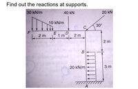
Find out the reactions at supports.

Transcribed Image Text:Find out the reactions at supports.
30 kN/m
40 kN
20 kN
10 kN/m
30°
C.
F
2 m 1 m 2m
E
2 m
B
20 kN/m
3 m
Expert Solution
This question has been solved!
Explore an expertly crafted, step-by-step solution for a thorough understanding of key concepts.
Step by stepSolved in 2 steps with 1 images

Knowledge Booster
Learn more about
Need a deep-dive on the concept behind this application? Look no further. Learn more about this topic, mechanical-engineering and related others by exploring similar questions and additional content below.Similar questions
- 300 mm² P=200 kN 200 mm 200 mm 400 mm² -250 mm E=123 x 10³ N/mm² (1 kN = 1000 N) Figure 2 Xarrow_forwardHelp with the questionarrow_forwardThree (3) different cylinder made from Steel, Aliminum and Bronze are jointed together to form a composite structure and fixed to wall support. Three (3) axial forces denoted as 4P, 2P and 2P acted on the structure as shown. The following value was already determined: Reaction at A =4 kN to the right Internal force for Bronze =2 kN compression Esteel = 200 GPa; EAlminum 70 GPa, EBrenz 83 GPa Determine the elongation ( 8 ) for each section: Aluminum A = 400 mm? Bronze Steel A = 200 mm? A = 500 mm? 2P 4P 2P 2.5 m 2.0 m 1.5 marrow_forward
- For the structural beam loaded and supported as shown in Figure 2, (a) Draw a free body diagram and find the support reaction forces/moments.arrow_forwardHow can the shear force, be determined from the method of sections andthe equations of equilibrium?arrow_forwardA alank of wood is fixed to a wall using a hinge. When the angle between the plank and the wall is 45°, a spring is attached to the wood 25cm from the hinge and fixed to the wall so that it is horizontal (Diagram A). The wood is then pushed downwards until it is perpendicular to the wall (Diagram B). The force exerted by the spring, depends on its length. As the spring stretches, the force it exerts increases. A graph showing this relationship is below. 70 Diagram B 60 Diagram A spring 50 90° 20 25cm 45 90° 10 25cm hinge 10 35 15 20 25 30 Spring Length (cm) (a) Calculate the length of the spring in Diagrams A and B. (b) Calculate the torque produced by the spring on the plank of compare the values. around the hinge in 4 oth Diagrams A and B and Force (N)arrow_forward
arrow_back_ios
arrow_forward_ios
Recommended textbooks for you
 Elements Of ElectromagneticsMechanical EngineeringISBN:9780190698614Author:Sadiku, Matthew N. O.Publisher:Oxford University Press
 Mechanics of Materials (10th Edition)Mechanical EngineeringISBN:9780134319650Author:Russell C. HibbelerPublisher:PEARSON
 Thermodynamics: An Engineering ApproachMechanical EngineeringISBN:9781259822674Author:Yunus A. Cengel Dr., Michael A. BolesPublisher:McGraw-Hill Education
 Control Systems EngineeringMechanical EngineeringISBN:9781118170519Author:Norman S. NisePublisher:WILEY
 Mechanics of Materials (MindTap Course List)Mechanical EngineeringISBN:9781337093347Author:Barry J. Goodno, James M. GerePublisher:Cengage Learning
 Engineering Mechanics: StaticsMechanical EngineeringISBN:9781118807330Author:James L. Meriam, L. G. Kraige, J. N. BoltonPublisher:WILEY

Elements Of Electromagnetics
Mechanical Engineering
ISBN:9780190698614
Author:Sadiku, Matthew N. O.
Publisher:Oxford University Press

Mechanics of Materials (10th Edition)
Mechanical Engineering
ISBN:9780134319650
Author:Russell C. Hibbeler
Publisher:PEARSON

Thermodynamics: An Engineering Approach
Mechanical Engineering
ISBN:9781259822674
Author:Yunus A. Cengel Dr., Michael A. Boles
Publisher:McGraw-Hill Education

Control Systems Engineering
Mechanical Engineering
ISBN:9781118170519
Author:Norman S. Nise
Publisher:WILEY

Mechanics of Materials (MindTap Course List)
Mechanical Engineering
ISBN:9781337093347
Author:Barry J. Goodno, James M. Gere
Publisher:Cengage Learning

Engineering Mechanics: Statics
Mechanical Engineering
ISBN:9781118807330
Author:James L. Meriam, L. G. Kraige, J. N. Bolton
Publisher:WILEY