Elements Of Electromagnetics
7th Edition
ISBN: 9780190698614
Author: Sadiku, Matthew N. O.
Publisher: Oxford University Press
expand_more
expand_more
format_list_bulleted
Concept explainers
Question
answer this ;
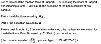
Let ? represent the reaction force at Support B. By releasing the beam at Support B and imposing a force ? at Point B, the deflection of the beam consists of two parts,i.e.
Part I- the deflection caused by ?? ;
Part II- the deflection caused by ?
Please treat R, w, h , L , E as variables in this step , the mathematical equation for the deflection at Point B caused by ? ( Part II) can be written as
(Hint : to input equation ?2??2?ℎ , you can type (R^2*L)/(Q^2*w*h) )

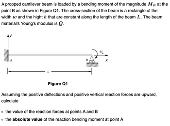
Transcribed Image Text:A propped cantilever beam is loaded by a bending moment of the magnitude MB at the
point B as shown in Figure Q1. The cross-section of the beam is a rectangle of the
width w and the hight h that are constant along the length of the beam L. The beam
material's Young's modulus is Q.
AY
1
A
B
MB
X
Figure Q1
Assuming the positive deflections and positive vertical reaction forces are upward,
calculate
o the value of the reaction forces at points A and B
o the absolute value of the reaction bending moment at point A

Transcribed Image Text:Let R represent the reaction force at Support B. By releasing the beam at Support B
and imposing a force R at Point B, the deflection of the beam consists of two
parts,i.e.
Part I- the deflection caused by MB;
Part II- the deflection caused by R
Please treat R, w, h, L, E as variables in this step, the mathematical equation for
the deflection at Point B caused by R (Part II) can be written as
(Hint: to input equation
R² L
Q² wh
"
you can type (R^2*L)/(Q^2*w*h) )
Expert Solution
This question has been solved!
Explore an expertly crafted, step-by-step solution for a thorough understanding of key concepts.
Step by stepSolved in 3 steps with 4 images

Knowledge Booster
Learn more about
Need a deep-dive on the concept behind this application? Look no further. Learn more about this topic, mechanical-engineering and related others by exploring similar questions and additional content below.Similar questions
- For the beam and loading shown, use the double-integration method to determine (a) the equation of the elastic curve for the cantilever beam AB, (b) the deflection at the free end, and (c) the slope at the free end. Assume that El is constant for the beam. Let wo = 9 kN/m, L = 5.5 m, E = 220 GPa, and I = 100 x 10° mm“. |B L Part 1 Incorrect Cut a cross-section through the beam at any point and draw a free body diagram to the right of your cut. Determine the internal bending moment M(x). The diagram shows M(x) in its positive direction. Your answer may be negative. Check your equation by solving for M at x = 2.8 m. Wo M(x) |B L-x Answer: M(x = 2.8 m) = i ! kN-marrow_forward3) An L-shaped solid round bracket has the properties E, G, A, I, and J. The bracket below is loaded with a torque about the Z-axis at the free end and a force in the Y direction. A) Derive an expression for the deflection of the free end in the Y-direction (Dummy load F=0 shown)? B) Calculate the deflection in the Y-direction if the L-shaped round bracket is made from aluminum with a= 12 in, b = 6 in, d = 0.75 in, and T = 30 in-lb. F X Solid round rod of properties E, G, A, I, and J.arrow_forwardA 3 meter beam mounted on the skid located at A and the articulation at point B,supports a set of distributed loads, as shown in Figure 3. For thedisplayed loading conditions, determine:a) The applied forces equivalent to the distributed loads and their locations.b) The reactions in the skid at A and the joint at B.Consider:a) The load distribution changes at point C, located 1 meter from point Ahorizontally.b) The skid at A is 25 cm from the left edge of the beam.c) The separation between the supports is 1.5 meters.d) The distributed load begins at point A and ends 75 cm before the other end of the beam.arrow_forward
- The motor compartment rail must meet the package constraints imposed by the suspension and powertrain. These constraints often force nonsymmetrical loading and section shape. For the illustrations shown in a and b determine the deflection at the tip of the beam and maximum direct stress and location for a 2000-N load. 40 x 80 x 1.5 mm 1 m Engine (a) Load application at centroid 2 |15° Section rotated 15°. Load application point through centroid of section (b) Enginearrow_forwardProblem 1: (Please solve parts A and B of problem) A) A uniformly distributed load is subjected on the clamped-clamped beam and it is supported by a spring in the middle of the beam. Using Castigliano’s theorem, find the deflection in the spring. (Please use only Castigliano’s theorem to solve this part) B) Remove the spring in part A and use the Rayleigh-Ritz method to solve for the deflection at the middle of the beam. Assume that v(x) = C (1- Cos((2Pi*x)/L)) (Please use only Rayleigh-Ritz method for this part)arrow_forwardA) Calculate the stress in each link when a force of 600 lbs is applied to the rigid element AF, employing manual calculations and finite element methods. B) Determine the corresponding deflection at point A, manually applying the finite element penalty method to model and solve the constraints effectively. Available Data: The links BC and DE are made of steel. Each link has dimensions of 1/2 inch in width and 1/4 inch in thickness. Modulus of elasticity (E): 29 x 10^6 psi. Instructions: For this problem, manual calculation is crucial. Utilize the finite element method with the penalty approach to handle boundary conditions and constraints effectively. This method involves incorporating penalty factors into the system equations to enforce the constraints strictly.arrow_forward
- Please help with this questions parts A and B. :))arrow_forwardPlease use sigularity function to estimate the maximum deflection at the point of applying load Parrow_forwardA D В C__0 L L· For the following beam, a) Use the method of superposition to determine the reactions at the supports B and C. (El is constant) b) Find the rotation at D. L=1.25mm W=2.5kN/marrow_forward
- In the position shown in figure shown, the block of mass 100 kg just contacts the free end of the spring with constant k-6000N/m (a) If the block is released instantaneously with zero initial velocity, find the m lection of the spring (b) Find the max deflection, if the block is very gradually lowered onto spring. 100kg Free end ANS: a.)|| m b.) m (two decimal places)arrow_forwardDetermine the reactions present at the pin A and roller B required for equilibrium of the beam. (Final Answers – signs depend on FBD: Ay = 2230 N, Ax = 0, B = 2170Narrow_forwardPin-joint construction supports point loads as shown below: P Al ΕΙ C B 2/3 L 1/3 L a) Find the equation for the deflection of the bar at point B! b) Determine the equation for the moment that occurs at point A!arrow_forward
arrow_back_ios
SEE MORE QUESTIONS
arrow_forward_ios
Recommended textbooks for you
 Elements Of ElectromagneticsMechanical EngineeringISBN:9780190698614Author:Sadiku, Matthew N. O.Publisher:Oxford University Press
 Mechanics of Materials (10th Edition)Mechanical EngineeringISBN:9780134319650Author:Russell C. HibbelerPublisher:PEARSON
 Thermodynamics: An Engineering ApproachMechanical EngineeringISBN:9781259822674Author:Yunus A. Cengel Dr., Michael A. BolesPublisher:McGraw-Hill Education
 Control Systems EngineeringMechanical EngineeringISBN:9781118170519Author:Norman S. NisePublisher:WILEY
 Mechanics of Materials (MindTap Course List)Mechanical EngineeringISBN:9781337093347Author:Barry J. Goodno, James M. GerePublisher:Cengage Learning
 Engineering Mechanics: StaticsMechanical EngineeringISBN:9781118807330Author:James L. Meriam, L. G. Kraige, J. N. BoltonPublisher:WILEY

Elements Of Electromagnetics
Mechanical Engineering
ISBN:9780190698614
Author:Sadiku, Matthew N. O.
Publisher:Oxford University Press

Mechanics of Materials (10th Edition)
Mechanical Engineering
ISBN:9780134319650
Author:Russell C. Hibbeler
Publisher:PEARSON

Thermodynamics: An Engineering Approach
Mechanical Engineering
ISBN:9781259822674
Author:Yunus A. Cengel Dr., Michael A. Boles
Publisher:McGraw-Hill Education

Control Systems Engineering
Mechanical Engineering
ISBN:9781118170519
Author:Norman S. Nise
Publisher:WILEY

Mechanics of Materials (MindTap Course List)
Mechanical Engineering
ISBN:9781337093347
Author:Barry J. Goodno, James M. Gere
Publisher:Cengage Learning

Engineering Mechanics: Statics
Mechanical Engineering
ISBN:9781118807330
Author:James L. Meriam, L. G. Kraige, J. N. Bolton
Publisher:WILEY