Introductory Circuit Analysis (13th Edition)
13th Edition
ISBN: 9780133923605
Author: Robert L. Boylestad
Publisher: PEARSON
expand_more
expand_more
format_list_bulleted
Question

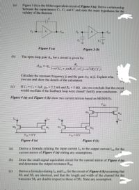
Transcribed Image Text:Figure 3 (b) is the Miller equivalent circuit of Figure 3 (a). Derive a relationship
between the capacitances C, C: and C and state the main hypothesis for the
valıdity of the theorem.
Figure 3 (a)
Figure 3 (b)
(b)
The open loop gain A,, for a circuit is given by:
AOL-8
* JAR (C, +G1-erLR CC,)
Calculate the resonant frequency fi and the gain Aot at Explain wha.
you use and show the details of the calculation.
(e)
If C=Cy= IpF, g2.2 mS and R,5 k2, can you conclude that the circuit
would oscillate if the feedback loop were closed Justify your conclusion, 1
Figure 4 (a) and Figure 4 (b) show two current mirrors based on MOSFETS
Ma
Ms
Figure 4 (a)
Figure 4 (b)
(a)
Derive a formula relating the input current I, to the output current I for the
current mirror of Figure 4 (a) stating any assumptions.
(b)
Draw the small-signal equivalent circuit for the current mirror of Figure 4 (a)
and determine the output resistance R
Derive a formula relating I and L for the circuit of Figure 4 (b) assuming that
(c)
Mi and Ma are identical, and that the length and width of the channel for the
transistor Ma are double respect to those of M3. State any assumption.
Expert Solution
This question has been solved!
Explore an expertly crafted, step-by-step solution for a thorough understanding of key concepts.
Step by stepSolved in 5 steps with 3 images

Knowledge Booster
Learn more about
Need a deep-dive on the concept behind this application? Look no further. Learn more about this topic, electrical-engineering and related others by exploring similar questions and additional content below.Similar questions
- A pn junction has NA >> ND . We expect that: There is no depletion region, since NA * ND. The depletion region is wider in the p-type material than in the n-type material. The depletion region width is equal in the n-type and p-type regions. The depletion region is wider in the n-type material than in the p-type material.arrow_forward2. Explain which of the following instructions are invalid? State the invalidation reason and give the correct form for invalid instructions: a. MOV DL,AX b. MOV ES,CX c. MOV [BX],[2000] d. MOV BX,[AX] e. MOV CL,[BL+200] f. MOV 1234,DX g. MOV CH,[BX+SI+300] h. MOV DS,[SI+DI-5] i. MOV [4500],1234 j. MOV 200,[300]arrow_forwardASAP plzarrow_forward
- Consider the following circuit with Vs(t) = 2.0 + 0.02 sin(2 pi t) V,R1 = R2 = 25ohms Idc = 1mA, Vdc = 5V. Assume Vy = 0.7V and VT = 25mV.a) Draw the equivalent circuit under DCb) Determine the DC voltage and current through the diode.c) Draw the equivalent circuit under acd) Determine the total current through the diodearrow_forwardCalculate the total current of a circuit with a 9.5 V voltage source connected in series with a directly biased silicon diode and a series resistor of 440 Ω. Consider the second approximation of the diode where it is considered to be connected to a battery in series. Units of the response in milli amperes. Note: I put the original exercise in Spanish, so that it is better understood. Explain step by step, please.arrow_forward
arrow_back_ios
arrow_forward_ios
Recommended textbooks for you
 Introductory Circuit Analysis (13th Edition)Electrical EngineeringISBN:9780133923605Author:Robert L. BoylestadPublisher:PEARSON
 Delmar's Standard Textbook Of ElectricityElectrical EngineeringISBN:9781337900348Author:Stephen L. HermanPublisher:Cengage Learning
 Programmable Logic ControllersElectrical EngineeringISBN:9780073373843Author:Frank D. PetruzellaPublisher:McGraw-Hill Education
 Fundamentals of Electric CircuitsElectrical EngineeringISBN:9780078028229Author:Charles K Alexander, Matthew SadikuPublisher:McGraw-Hill Education
 Electric Circuits. (11th Edition)Electrical EngineeringISBN:9780134746968Author:James W. Nilsson, Susan RiedelPublisher:PEARSON
 Engineering ElectromagneticsElectrical EngineeringISBN:9780078028151Author:Hayt, William H. (william Hart), Jr, BUCK, John A.Publisher:Mcgraw-hill Education,

Introductory Circuit Analysis (13th Edition)
Electrical Engineering
ISBN:9780133923605
Author:Robert L. Boylestad
Publisher:PEARSON

Delmar's Standard Textbook Of Electricity
Electrical Engineering
ISBN:9781337900348
Author:Stephen L. Herman
Publisher:Cengage Learning

Programmable Logic Controllers
Electrical Engineering
ISBN:9780073373843
Author:Frank D. Petruzella
Publisher:McGraw-Hill Education

Fundamentals of Electric Circuits
Electrical Engineering
ISBN:9780078028229
Author:Charles K Alexander, Matthew Sadiku
Publisher:McGraw-Hill Education

Electric Circuits. (11th Edition)
Electrical Engineering
ISBN:9780134746968
Author:James W. Nilsson, Susan Riedel
Publisher:PEARSON

Engineering Electromagnetics
Electrical Engineering
ISBN:9780078028151
Author:Hayt, William H. (william Hart), Jr, BUCK, John A.
Publisher:Mcgraw-hill Education,