Concept explainers
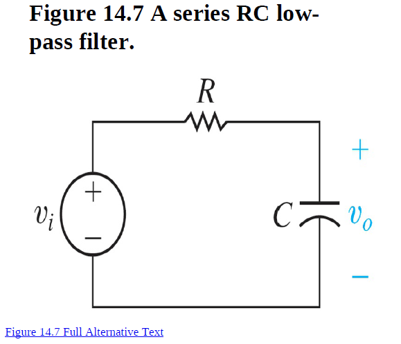
Design a passive RC low pass filter (14.7) with a cutoff
frequency of 100 Hz using a 4.7 μF capacitor.
1. a) What is the cutoff frequency in rad/s? 2. b) What is the value of the resistor?
3. c) Draw your circuit, labeling the component values and output
voltage.
4. d) What is the transfer function of the filter in part (c)?
5. e) If the filter in part (c) is loaded with a resistor whose value is the
same as the resistor part (b), what is the transfer function of this
loaded filter?
6. f) What is the cutoff frequency of the loaded filter from part (e)?
7. g) What is the gain in the pass band of the loaded filter from part
(e)?

Trending nowThis is a popular solution!
Step by stepSolved in 2 steps with 1 images

- Need Hand Drawn Pleasearrow_forwardPlease answer all subpart either dislike is ready Please all This is one question..arrow_forward3. Active Analog Filter Topologies You already know from our class discussions that Circuit 1 is an active analog Low-Pass Filter For each of the remaining three circuits, state whether the circuit will function as a low-pass or high-pass filter. Each of your answers must be accompanied by a brief explanation and justification incorporating the frequency dependent characteristics of the reactive circuit elements. That is you should look at the asymptotic impedance of the L and C if the input signal the frequency is very low or very high. Sketch the expected Bode plot for 20 log(Vo/Vs) as a function of log (f) labeling the corner frequencies. No equations are required! R2 R2 R2 R2 R1 R1 R1 Vs Vs o W- Vs Vs Vo Vo Vo Vo Circuit 1 Citcuit 2 Circuit 3 Circuit 4arrow_forward
 Introductory Circuit Analysis (13th Edition)Electrical EngineeringISBN:9780133923605Author:Robert L. BoylestadPublisher:PEARSON
 Delmar's Standard Textbook Of ElectricityElectrical EngineeringISBN:9781337900348Author:Stephen L. HermanPublisher:Cengage Learning
 Programmable Logic ControllersElectrical EngineeringISBN:9780073373843Author:Frank D. PetruzellaPublisher:McGraw-Hill Education
 Fundamentals of Electric CircuitsElectrical EngineeringISBN:9780078028229Author:Charles K Alexander, Matthew SadikuPublisher:McGraw-Hill Education
 Electric Circuits. (11th Edition)Electrical EngineeringISBN:9780134746968Author:James W. Nilsson, Susan RiedelPublisher:PEARSON
 Engineering ElectromagneticsElectrical EngineeringISBN:9780078028151Author:Hayt, William H. (william Hart), Jr, BUCK, John A.Publisher:Mcgraw-hill Education,


