Structural Analysis
6th Edition
ISBN: 9781337630931
Author: KASSIMALI, Aslam.
Publisher: Cengage,
expand_more
expand_more
format_list_bulleted
Question
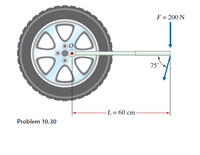
The tire wrench shown in the accompanying figure is used to tighten the bolt
on a wheel. Given the information on the diagram, determine the moment about point O for the two loading situations shown:
a. pushing perpendicular to the wrench arm
b. pushing at a 75° angle.

Transcribed Image Text:F = 200 N
75°
-L = 60 cm-
Problem 10.30
Expert Solution
This question has been solved!
Explore an expertly crafted, step-by-step solution for a thorough understanding of key concepts.
This is a popular solution
Trending nowThis is a popular solution!
Step by stepSolved in 4 steps with 2 images

Knowledge Booster
Learn more about
Need a deep-dive on the concept behind this application? Look no further. Learn more about this topic, civil-engineering and related others by exploring similar questions and additional content below.Similar questions
- 6- The propeller of a ship is to be studied with a 1:15 scale model. (a) Assume the propeller operate close to the surface, select the propeller speed of the model if the prototype is 600 rpm. (b) What torque would be expected if 1.2 Nm is measured on the model?arrow_forwardWhat is the resulting force from the distributed load shown below? 400 N/m -3 m- O 1200 N/m 400 N/m O 200 N/m A O 2400 N/m 3 m Barrow_forwardA non-prismatic simply supported beam as shown in the figure is subjected to three point loading. The maximum deflection in the beam will be places) I L/3 B Ba 21 L/3 PL(round off to three decimal |² I с L/3arrow_forward
- Acompound shaft drives several pulleys, as shown in the figure. Segments (1) and (2) of the compound shaft are hollow aluminum [G=4,000 ksi] tubes that have a polar moment of inertia of 2.337 in.4. Segments (3) and (4) are solid steel [G=12,000 ksi] shafts that have a polar moment of inertia of 0.497 in.. The bearings shown allow the shaft to turn freely. Calculate the rotation angle (including the correct sign) of pulley Dwith respect to pulley & 175 lb-ft 20 in. 525 lb-ft D 40 in. 925 lb-ft 30 in. (1) 70 in.arrow_forwardRequired information NOTE: This is a multi-part question. Once an answer is submitted, you will be unable to return to this part. A 4500-lb forklift truck is used to lift a 1700-lb crate. -16 in.- 1. 24 in. 12 in. Determine the reaction at each of the two rear wheels B. The reaction at the rear wheels Bis ib.arrow_forwardPlease answer the attached image Thank youarrow_forward
- The beam in the figure on the right is subjected to the loading profile shown. Determine all reactions on the beam, show clear diagrams. Do not use sine and cosine functions in your calculation. Only geometry rations.arrow_forwardProblem 4.91 The couple moment acting on the pipe has a magnitude of 300 Nm . (Figure 1) Figure 1 -F A ▼ of 1 -150 mm. 150 mm. B 200 mm 600 mm > Part A Determine the magnitude F of the forces applied to the wrenches. Express your answer to three significant figures and include the appropriate units. F = 153 Submit μà N My Answers Give Up ? Incorrect; Try Again; 3 attempts remainingarrow_forwardThe diagram below shows a bicycle brake lever that has been pulled with a 35 N force to apply the brake. calculate the moment of the force applied by the cyclist about the pivot. state an appropriate unit. brake cable 110mm force applied by cyclist tension 25 mm brake lever pivot 35 N handle bararrow_forward
- A crate with a mass of 250 kg is held in equilibrium by three ropes attached to a steel ring. a d3 d₁ d5 B A 5.5 m 4 m d2 3.5 m 2m d₁ Z 3 Values for the figure are given in the following table. Note the figure may not be to scale. Variable Value d₁ 2 m d₂ d4 a. Determine the magnitude of the force/tension in cord A, TA. b. Determine the magnitude of the force/tension in cord B, TB. c. Determine the magnitude of the force/tension in cord C, Tc. Round your final answers to 3 significant digits/figures. The magnitude of the force/tension in cord A is The magnitude of the force/tension in cord B is The magnitude of the force/tension in cord C' is d5 kN kN kNarrow_forwardneed helparrow_forwardShow complete solution.arrow_forward
arrow_back_ios
SEE MORE QUESTIONS
arrow_forward_ios
Recommended textbooks for you

 Structural Analysis (10th Edition)Civil EngineeringISBN:9780134610672Author:Russell C. HibbelerPublisher:PEARSON
 Principles of Foundation Engineering (MindTap Cou...Civil EngineeringISBN:9781337705028Author:Braja M. Das, Nagaratnam SivakuganPublisher:Cengage Learning
 Fundamentals of Structural AnalysisCivil EngineeringISBN:9780073398006Author:Kenneth M. Leet Emeritus, Chia-Ming Uang, Joel LanningPublisher:McGraw-Hill Education
 Traffic and Highway EngineeringCivil EngineeringISBN:9781305156241Author:Garber, Nicholas J.Publisher:Cengage Learning


Structural Analysis (10th Edition)
Civil Engineering
ISBN:9780134610672
Author:Russell C. Hibbeler
Publisher:PEARSON

Principles of Foundation Engineering (MindTap Cou...
Civil Engineering
ISBN:9781337705028
Author:Braja M. Das, Nagaratnam Sivakugan
Publisher:Cengage Learning

Fundamentals of Structural Analysis
Civil Engineering
ISBN:9780073398006
Author:Kenneth M. Leet Emeritus, Chia-Ming Uang, Joel Lanning
Publisher:McGraw-Hill Education


Traffic and Highway Engineering
Civil Engineering
ISBN:9781305156241
Author:Garber, Nicholas J.
Publisher:Cengage Learning