Elements Of Electromagnetics
7th Edition
ISBN: 9780190698614
Author: Sadiku, Matthew N. O.
Publisher: Oxford University Press
expand_more
expand_more
format_list_bulleted
Question

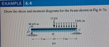
Transcribed Image Text:EXAMPLE 6.4
Draw the shear and moment diagrams for the beam shown in Fig. 6-7a.
15 kN
80 kN·m
-5 m
B
-5 m
(a)
5 kN/m
D
Expert Solution
This question has been solved!
Explore an expertly crafted, step-by-step solution for a thorough understanding of key concepts.
Step by stepSolved in 2 steps with 2 images

Knowledge Booster
Similar questions
- A fixed beam of length 3 m is subjected to the distributed load shown above. (A) state the reaction forces at A and C (B) Write the equations for bending moment and shear force at any section along the beam and draw the shear force and bending moment diagram. (C) State the maximal bending moment and shear force and their locations.arrow_forwardThe beam ABCD shown in the figure has overhangs that extend in both directions for a distance of 4.2m from the supports at B and C, which are 1.2m apart. Draw the shear-force and bending-moment diagrams for this overhanging beam.arrow_forwardThe cantilever beam in Fig. (a) carries a triangular load, the intensity of which varies from zero at the left end to 360 lb/ft at the right end. In addition, a 1000-lb upward vertical load acts at the free end of the beam. (1) Derive the shear force and bending moment equations, and (2) draw the shear force and bending moment diagrams. Neglect the weight of the beamarrow_forward
- The 8 m long cantilever beam shown in the figure below carries a uniformly distributed load of 10 kN/m over a span of 2 m, a uniformly varying load that varies linearly from zero to 20 kN/m over a span of 5 m, and a 15 kN concentrated load at the free end as shown. 1.1 Nearly sketch the shear force and bending moment diagrams 1.2 What is the maximum shear force and where does it occur? 1.3 What is the maximum bending moment and where does it occur? 1.4 Find any points of contraflexure. 20 kN/m 15 kN 10 kN/m 1 m 5 m 2 marrow_forwardDraw the normal force (N), shear force (T) and bending moment (M) diagrams of the beam whose span and loading condition are given in the figure. L3(m)=1.5 L4(m)=2 P3(kN)=44 P4(kN)=82arrow_forwardUnder cruising conditions, the distributed load acting on the wing of a small airplane has the idealized variation shown in the figure. Calculate the shear force Vand bending moment M at 4 m from the tip of the wing.arrow_forward
- Draw shear force and bending moment diagram of the beam loaded as shown in the figure. 20 kN 12 kN 1.5 kN/m A D 1.8 m 2.4 m 2.0 marrow_forwardsimply supported beam in Fig. (b) has a rectangular cross section 120 mm wide and 200 mm high. (a) Draw and calculate the sheer force and bending moment diagrams for given simply supported beams. (b) Compute the maximum bending stress in the beams and sketch the bending stress distribution over the cross section on which the maximum bending stress occurs.arrow_forwardQ3: Draw the shear force and bending moment diagrams for the loaded beam shown (see figure below). ( 125 kN 50 kN/m А B C 3 m 12 marrow_forward
- Q1 A A simply supported beam carries a UDL of 25 kN/m over the entire span of the beam is shown in Fig. 6. If the maximum bending stress is 60 MPa, find the span of the beam. Also find the maximum shear stress developed in the section. Draw the shear stress distribution diagram. 200mm ,w = 25kN/m 50mm - 250mm (a) (b) B Derive the flexure (Bending) formula.arrow_forwardQ3: Draw the shear force and bending moment diagrams for the loaded beam (shown (see figure below). (i : 125 kN 50 kN/m A В 3 m 12 marrow_forwardThe Simply supported beam in Figure has a rectangular cross section 120 mm wide and 200 mm high. (1)Compute the reaction forces Ra and Point RE. (2)Compute the maximum bending stress in the beam. - --- AAIL (4)Compute the bending stress at a point on section B that is 25 mm below the top of the beam. |15 kN 6 kN/m 100 mm NA - В ID 100 mm 0.8 m 120 mm 2 m 1.0 m RA RE (a)arrow_forward
arrow_back_ios
SEE MORE QUESTIONS
arrow_forward_ios
Recommended textbooks for you
 Elements Of ElectromagneticsMechanical EngineeringISBN:9780190698614Author:Sadiku, Matthew N. O.Publisher:Oxford University Press
 Mechanics of Materials (10th Edition)Mechanical EngineeringISBN:9780134319650Author:Russell C. HibbelerPublisher:PEARSON
 Thermodynamics: An Engineering ApproachMechanical EngineeringISBN:9781259822674Author:Yunus A. Cengel Dr., Michael A. BolesPublisher:McGraw-Hill Education
 Control Systems EngineeringMechanical EngineeringISBN:9781118170519Author:Norman S. NisePublisher:WILEY
 Mechanics of Materials (MindTap Course List)Mechanical EngineeringISBN:9781337093347Author:Barry J. Goodno, James M. GerePublisher:Cengage Learning
 Engineering Mechanics: StaticsMechanical EngineeringISBN:9781118807330Author:James L. Meriam, L. G. Kraige, J. N. BoltonPublisher:WILEY

Elements Of Electromagnetics
Mechanical Engineering
ISBN:9780190698614
Author:Sadiku, Matthew N. O.
Publisher:Oxford University Press

Mechanics of Materials (10th Edition)
Mechanical Engineering
ISBN:9780134319650
Author:Russell C. Hibbeler
Publisher:PEARSON

Thermodynamics: An Engineering Approach
Mechanical Engineering
ISBN:9781259822674
Author:Yunus A. Cengel Dr., Michael A. Boles
Publisher:McGraw-Hill Education

Control Systems Engineering
Mechanical Engineering
ISBN:9781118170519
Author:Norman S. Nise
Publisher:WILEY

Mechanics of Materials (MindTap Course List)
Mechanical Engineering
ISBN:9781337093347
Author:Barry J. Goodno, James M. Gere
Publisher:Cengage Learning

Engineering Mechanics: Statics
Mechanical Engineering
ISBN:9781118807330
Author:James L. Meriam, L. G. Kraige, J. N. Bolton
Publisher:WILEY