Introductory Circuit Analysis (13th Edition)
13th Edition
ISBN: 9780133923605
Author: Robert L. Boylestad
Publisher: PEARSON
expand_more
expand_more
format_list_bulleted
Question

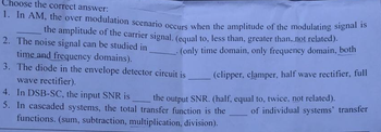
Transcribed Image Text:Choose the correct answer:
1. In AM, the over modulation scenario occurs when the amplitude of the modulating signal is
the amplitude of the carrier signal. (equal to, less than, greater than, not related).
2. The noise signal can be studied in
time and frequency domains).
(only time domain, only frequency domain, both
3. The diode in the envelope detector circuit is
wave rectifier).
(clipper, clamper, half wave rectifier, full
the output SNR. (half, equal to, twice, not related).
4. In DSB-SC, the input SNR is
5. In cascaded systems, the total transfer function is the
functions. (sum, subtraction, multiplication, division).
of individual systems' transfer
Expert Solution
This question has been solved!
Explore an expertly crafted, step-by-step solution for a thorough understanding of key concepts.
Step by stepSolved in 2 steps

Knowledge Booster
Similar questions
- In Amplitude Demodulation ( Envlope Detector )arrow_forwardb. Calculate the following about the circuit in the figure (If silicon diodes are employed in the rectification);i. the peak value of the output voltage considering the drop across each diode, Vpk.ii. the average voltage, Vdc. iii. The current through the load resistor, IL.iv. The current diode, Id.v. The frequency of the output signal, Fout.vi. Calculate the efficiency of the full wave rectifier expressed in percentage. vii. Sketch a graph of the input and output voltage against time.arrow_forwardDiscuss the principle of operation of a varactor diode and its applications in frequency - modulated circuits.arrow_forward
- h) Draw a generic transfer curve for a diode. Define breakdown voltage, zener region, threshold value of a diode and show these elements on the curve. i) Explain the conditions of cut-off, saturation and linear region of a transistor and show on the transfer curve j) What is avalanche current? Explain.arrow_forwardexplain how a pm signal is produced using a varactor diode in a phase modulator circuitarrow_forwardA 6.3V AC signal is half-wave rectified and applied to a 33-ohm load resistance. Determine the peak load voltage, the average load voltage, and the average current.Determine also what diode would be optimized to use in this circuit.arrow_forward
- (1) Sketch the circuit for an ac supply input to a full-wave diode rectifier with a resistive load and no smoothing capacitor. (2).Sketch the ac supply voltage and the voltage across the resistive load in (question no 1)indicating the period of the resistive load voltage. (3) For the circuit in (question no 1) calculate the average and rms voltages across the resistive load for an rms ac supply voltage of 115 V assuming no diode voltage.arrow_forwardPlease respond to parts (C), (D), and (F) in the attached image.arrow_forwardd.c. load line. It is the line on the output characteristics of a transistor circuit which gives the values of IC and VCE when signal is applied when no signal is applied O corresponding to a.c. conditions. other A half wave rectifier is equivalent to a clamper circuit. a clipper circuit. a clamper circuit with positive bias a clamper circuit with negative biasd. Oarrow_forward
- The positive peak value of output waveform for the given circuit diagram is.. (VPP of input is 18 V, Bias voltage is 3 V, Diode is germanium) R: D, VIN VouUT VaASarrow_forwardExample Full wave rectifier)) for the signal shown plot the amplitude specturm -T=0.4 for 2.6M²/ 5.41 weez fo -5T redbr ~0.4 -0.2 XCD) Vm 0.2 0.4arrow_forward4. Draw and explain the circuit of a simple AM demodulator using Junction diode ( draw the input and output waveforms )arrow_forward
arrow_back_ios
SEE MORE QUESTIONS
arrow_forward_ios
Recommended textbooks for you
 Introductory Circuit Analysis (13th Edition)Electrical EngineeringISBN:9780133923605Author:Robert L. BoylestadPublisher:PEARSON
 Delmar's Standard Textbook Of ElectricityElectrical EngineeringISBN:9781337900348Author:Stephen L. HermanPublisher:Cengage Learning
 Programmable Logic ControllersElectrical EngineeringISBN:9780073373843Author:Frank D. PetruzellaPublisher:McGraw-Hill Education
 Fundamentals of Electric CircuitsElectrical EngineeringISBN:9780078028229Author:Charles K Alexander, Matthew SadikuPublisher:McGraw-Hill Education
 Electric Circuits. (11th Edition)Electrical EngineeringISBN:9780134746968Author:James W. Nilsson, Susan RiedelPublisher:PEARSON
 Engineering ElectromagneticsElectrical EngineeringISBN:9780078028151Author:Hayt, William H. (william Hart), Jr, BUCK, John A.Publisher:Mcgraw-hill Education,

Introductory Circuit Analysis (13th Edition)
Electrical Engineering
ISBN:9780133923605
Author:Robert L. Boylestad
Publisher:PEARSON

Delmar's Standard Textbook Of Electricity
Electrical Engineering
ISBN:9781337900348
Author:Stephen L. Herman
Publisher:Cengage Learning

Programmable Logic Controllers
Electrical Engineering
ISBN:9780073373843
Author:Frank D. Petruzella
Publisher:McGraw-Hill Education

Fundamentals of Electric Circuits
Electrical Engineering
ISBN:9780078028229
Author:Charles K Alexander, Matthew Sadiku
Publisher:McGraw-Hill Education

Electric Circuits. (11th Edition)
Electrical Engineering
ISBN:9780134746968
Author:James W. Nilsson, Susan Riedel
Publisher:PEARSON

Engineering Electromagnetics
Electrical Engineering
ISBN:9780078028151
Author:Hayt, William H. (william Hart), Jr, BUCK, John A.
Publisher:Mcgraw-hill Education,