
Introductory Circuit Analysis (13th Edition)
13th Edition
ISBN: 9780133923605
Author: Robert L. Boylestad
Publisher: PEARSON
expand_more
expand_more
format_list_bulleted
Related questions
Question
The circuit given in the figure below is continuously sinusoidal and the element values in the circuit are e (t) = 2Cos (t + 90) volts, C = 1F, L = 2H, R1 = 1Ω, R2 = 2Ω.
a) Find the Thevenin equivalent of the circuit in the form V = ZThI + VTh, viewed from the A-B ends looking left.
b) Maximum active power is desired to be transferred to the Zload impedance connected to A-B terminals. What should be the Zload impedance? Calculate the maximum active power transferred to the load for this impedance value.
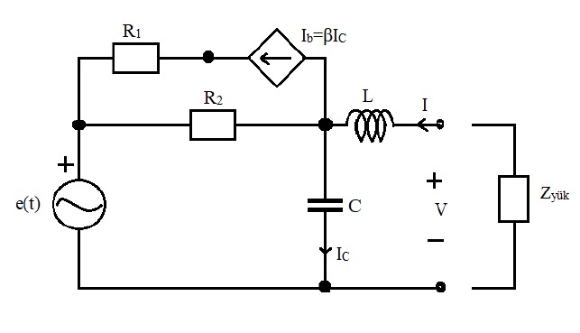

Transcribed Image Text:R1
Ib-BIc
R2
+
+
Zyük
e(t)
C
V
'Ic
Expert Solution
This question has been solved!
Explore an expertly crafted, step-by-step solution for a thorough understanding of key concepts.

Step by stepSolved in 10 steps with 10 images

Knowledge Booster


Learn more about
Need a deep-dive on the concept behind this application? Look no further. Learn more about this topic, electrical-engineering and related others by exploring similar questions and additional content below.Similar questions
- A 100-mH inductor is connected in parallel to the series connection of a variable resistor R and a 20-pF capacitor. The circuit is energized by a 120 Vac, 60-Hz supply. Find the value of R such that the total circuit current is 2.302305Z - 86.6782 A.arrow_forwardA step up dc/dc converter has input voltage Vs = 9 V, the average output voltage Va = 15 average load current la = 0.8 A. The switching frequency is f = 20 kHz, inductance is L = 0.3 mH and the parallel capacitance is C = 0.44 mF. Which one is the ripple current of inductor, Al ?arrow_forwardPlease correct and clean solution and both part are solvearrow_forward
- Question 1: a) Sketch Vo versus time for the circuit shown with the input given. b) Determine DC output voltage without a capacitor. c) If a capacitor of 10 uF is placed in parallel with RL, sketch the vo versus time. d) find the DC output voltage. Given R1 = R2 = RL = 2.2 k2. Vi +40 D1. D2 10 ms R = 2.2 k2 ww R%3D 1GF R = -40 2.2 k2 2.2 k2arrow_forwardConsider the series R-L circuit shown in figure below. For obtaining transient free response, switch should be closed at instant t = to. Find the value of to. (consider R = wL) t=to 2sin 8t R vor Larrow_forwardFor the circuit shown in Figure If Vec= 35 v, Is= 3.88mA. 30oksr Vs = (dg) Veco 3 RE find VRC and VRB and RE and value of Betaarrow_forward
- 5. The clock frequency in the switched-capacitor circuit in the below figure is 100 kHz. Find the equivalent resistance when: (a) C = 1pF, (b) C = 10pF, and (c) C = 30pF. V₁ M₂ V₂arrow_forward8) la Ix (Amps) Consider the following circuit and the associated IV curves. Assume that Is = 500fA and VT = .025V. a) Determine when la = 60uA and Vx = 3V. Show your work! b) Determine a when la = 60uA and Vx=3V. Show your work! c) Determine Vbe when la = 60uA and Vx=3V. Show your work! You may use the approximations that were presented in class and additionally you may neglect Va. Ix 8.00E-03 7.00E-03 6.00E-03 5.00E-03 4.00E-03 3.00E-03 2.00E-03 1.00E-03 0.00E+00 0 0.5 Vx 1 1.5 2 2.5 Vx (Volts) 3 3.5 4 4.5 5 ·la = 0 -la = 20uA -la = 40uA la = 60uAarrow_forwardSolve for Vp and Vs. Show your complete solution. (When you try to simulate the circuit in LTSpice where (Vin=0 DC Offset, 10V amplitude, 1MHz frequency), Vp=8V and Vs=40V. I want to learn how to get these values by solving) Will upvote is complete solution and correct. Thank you.arrow_forward
- Solve for the value of RTH by removing the source voltage VS as seen in the figure below.arrow_forward3) Load for a circuit with direct current source voltage The waveform of the voltage generated on it is below shown. Source for this working circuit that is symmetrical The value of the voltage and load resistance is 100 V and 5Ω respectively.It is given as. Find what is required below. d) Find the effective value of the output voltage e) Total harmonic distortion in output voltageCalculate (THD)arrow_forwardi need the answer quicklyarrow_forward
arrow_back_ios
arrow_forward_ios
Recommended textbooks for you
- Introductory Circuit Analysis (13th Edition)Electrical EngineeringISBN:9780133923605Author:Robert L. BoylestadPublisher:PEARSON
 Delmar's Standard Textbook Of ElectricityElectrical EngineeringISBN:9781337900348Author:Stephen L. HermanPublisher:Cengage Learning
 Programmable Logic ControllersElectrical EngineeringISBN:9780073373843Author:Frank D. PetruzellaPublisher:McGraw-Hill Education
  Fundamentals of Electric CircuitsElectrical EngineeringISBN:9780078028229Author:Charles K Alexander, Matthew SadikuPublisher:McGraw-Hill Education
 Electric Circuits. (11th Edition)Electrical EngineeringISBN:9780134746968Author:James W. Nilsson, Susan RiedelPublisher:PEARSON
 Engineering ElectromagneticsElectrical EngineeringISBN:9780078028151Author:Hayt, William H. (william Hart), Jr, BUCK, John A.Publisher:Mcgraw-hill Education,
Introductory Circuit Analysis (13th Edition)
Electrical Engineering
ISBN:9780133923605
Author:Robert L. Boylestad
Publisher:PEARSON
Delmar's Standard Textbook Of Electricity
Electrical Engineering
ISBN:9781337900348
Author:Stephen L. Herman
Publisher:Cengage Learning
Programmable Logic Controllers
Electrical Engineering
ISBN:9780073373843
Author:Frank D. Petruzella
Publisher:McGraw-Hill Education
Fundamentals of Electric Circuits
Electrical Engineering
ISBN:9780078028229
Author:Charles K Alexander, Matthew Sadiku
Publisher:McGraw-Hill Education
Electric Circuits. (11th Edition)
Electrical Engineering
ISBN:9780134746968
Author:James W. Nilsson, Susan Riedel
Publisher:PEARSON
Engineering Electromagnetics
Electrical Engineering
ISBN:9780078028151
Author:Hayt, William H. (william Hart), Jr, BUCK, John A.
Publisher:Mcgraw-hill Education,