Structural Analysis
6th Edition
ISBN: 9781337630931
Author: KASSIMALI, Aslam.
Publisher: Cengage,
expand_more
expand_more
format_list_bulleted
Concept explainers
Question

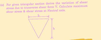
Transcribed Image Text:-(e) For given triangular section derive the variation of shear
stress due to transverse shear force V. Calculate maximum
shear stress & shear stress at Neutral axis.
b
Expert Solution
This question has been solved!
Explore an expertly crafted, step-by-step solution for a thorough understanding of key concepts.
Step by stepSolved in 3 steps with 3 images

Knowledge Booster
Learn more about
Need a deep-dive on the concept behind this application? Look no further. Learn more about this topic, civil-engineering and related others by exploring similar questions and additional content below.Similar questions
- The force P=25 kN is applied to the bracket as shown in the figure. Compute the normal stresses developed at points A and B. A Answer B 1000 mm 100 mm 17.5° P A = 8000 mm² I= 50 x 106 mm4 NA. T 100 mm 77 200 mmarrow_forwardA beam is subjected to equal bending moments of M₂ = 3300 N-m. The cross-sectional dimensions are b = 190 mm, c = 26 mm, d = 75 mm, and t = 5 mm. Determine: (a) the centroid location, the moment of inertia about the z axis, and the controlling section modulus about the z axis. (b) the bending stress at point H. Tensile stress is positive, while compressive stress is negative. (c) the bending stress at point K. Tensile stress is positive, while compressive stress is negative. (d) the maximum bending stress produced in the cross section. Tensile stress is positive, while compressive stress is negative. M₂ N y| M₂ (typ) Z- b H K darrow_forwardcan someone help?arrow_forward
- The control arm is subjected to the loading shown. The allowable shear stress for the steel pin is τ = 10 ksi. Determine the required diameters of the steel pins at A and C. Write your final answer to the nearest three decimal places.arrow_forwardConsider a cantilevered beam which is made of two identical. rectangular sections, a force P is applied at free end. 11) if A and B are not clued together, determine the bending stress distribution at a-a cross section, draw o Chint: each section carries P/ and label the Tout at the outest fibers. * 0.5m a 12) if we weld the two A & B together along the member length. determine the bending stress distribution, draw and laber. m ✓ P=1kw A 181- дет B зстarrow_forward
arrow_back_ios
arrow_forward_ios
Recommended textbooks for you

 Structural Analysis (10th Edition)Civil EngineeringISBN:9780134610672Author:Russell C. HibbelerPublisher:PEARSON
 Principles of Foundation Engineering (MindTap Cou...Civil EngineeringISBN:9781337705028Author:Braja M. Das, Nagaratnam SivakuganPublisher:Cengage Learning
 Fundamentals of Structural AnalysisCivil EngineeringISBN:9780073398006Author:Kenneth M. Leet Emeritus, Chia-Ming Uang, Joel LanningPublisher:McGraw-Hill Education
 Traffic and Highway EngineeringCivil EngineeringISBN:9781305156241Author:Garber, Nicholas J.Publisher:Cengage Learning


Structural Analysis (10th Edition)
Civil Engineering
ISBN:9780134610672
Author:Russell C. Hibbeler
Publisher:PEARSON

Principles of Foundation Engineering (MindTap Cou...
Civil Engineering
ISBN:9781337705028
Author:Braja M. Das, Nagaratnam Sivakugan
Publisher:Cengage Learning

Fundamentals of Structural Analysis
Civil Engineering
ISBN:9780073398006
Author:Kenneth M. Leet Emeritus, Chia-Ming Uang, Joel Lanning
Publisher:McGraw-Hill Education


Traffic and Highway Engineering
Civil Engineering
ISBN:9781305156241
Author:Garber, Nicholas J.
Publisher:Cengage Learning