
Introductory Circuit Analysis (13th Edition)
13th Edition
ISBN: 9780133923605
Author: Robert L. Boylestad
Publisher: PEARSON
expand_more
expand_more
format_list_bulleted
Related questions
Question
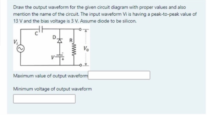

Transcribed Image Text:Draw the output waveform for the given circuit diagram with proper values and also
mention the name of the circuit. The input waveform Vi is having a peak-to-peak value of
13 V and the bias voltage is 3 V. Assume diode to be silicon.
Vị
Vo
Maximum value of output waveform
Minimum voltage of output waveform
www
Expert Solution
This question has been solved!
Explore an expertly crafted, step-by-step solution for a thorough understanding of key concepts.

This is a popular solution

Trending nowThis is a popular solution!

Step by stepSolved in 3 steps with 2 images

Knowledge Booster


Learn more about
Need a deep-dive on the concept behind this application? Look no further. Learn more about this topic, electrical-engineering and related others by exploring similar questions and additional content below.Similar questions
- 5. Draw the Input/Output Vin/ Vout characteristic curve of the circuit given below. However, assume a Constant Voltage Diode Model and VB = 2 V. D₁ R₁ W VB MI D₂ R₂ Voutarrow_forwardA silicon diode has 1 ampere DC of current in biasd mode. What is voltage drop across the diode?arrow_forwardDraw the output waveform for the given circuit diagram with proper values and also mention the name of the circuit. The input waveform Vi is having a peak-to-peak value of 17 V and the bias voltage is 4 V. Assume diode to be silicon. Vo Maximum value of output waveform Minimum voltage of output waveformarrow_forward
- Sketch the output waveform and indicate the expected voltage levels for each of these diode circuits below. Use the diode models as indicated.arrow_forwardshown below is a diode circuit. If the input signal Vs= 36Vp-p and the DC voltage Vdc = 4V, what is the output voltage (in volts) of the circuit during the positive alteration?arrow_forwardB. Assume (GaAs diode), determine and draw the output waveform of the Figure shown below. suggest adequate values of R and C if the input voltage frequency is 200 Hz. Input waveformarrow_forward
- Consider diode circuit shown below with Vcc=5V and V₂ = 3V. U₁A HH +V₂ ū The peak inverse voltage on the diode is close to V₁ V. A Voarrow_forwardA - Explain the symbols, operating principles and usage areas of the diodes given below. (Zener diode: photo diode: led diode: opto coupler) B- Draw the voltage trigger circuit and explain its operation. Explain how there is a difference between the voltage quadrant and the triplerarrow_forward
arrow_back_ios
arrow_forward_ios
Recommended textbooks for you
- Introductory Circuit Analysis (13th Edition)Electrical EngineeringISBN:9780133923605Author:Robert L. BoylestadPublisher:PEARSON
 Delmar's Standard Textbook Of ElectricityElectrical EngineeringISBN:9781337900348Author:Stephen L. HermanPublisher:Cengage Learning
 Programmable Logic ControllersElectrical EngineeringISBN:9780073373843Author:Frank D. PetruzellaPublisher:McGraw-Hill Education
  Fundamentals of Electric CircuitsElectrical EngineeringISBN:9780078028229Author:Charles K Alexander, Matthew SadikuPublisher:McGraw-Hill Education
 Electric Circuits. (11th Edition)Electrical EngineeringISBN:9780134746968Author:James W. Nilsson, Susan RiedelPublisher:PEARSON
 Engineering ElectromagneticsElectrical EngineeringISBN:9780078028151Author:Hayt, William H. (william Hart), Jr, BUCK, John A.Publisher:Mcgraw-hill Education,
Introductory Circuit Analysis (13th Edition)
Electrical Engineering
ISBN:9780133923605
Author:Robert L. Boylestad
Publisher:PEARSON
Delmar's Standard Textbook Of Electricity
Electrical Engineering
ISBN:9781337900348
Author:Stephen L. Herman
Publisher:Cengage Learning
Programmable Logic Controllers
Electrical Engineering
ISBN:9780073373843
Author:Frank D. Petruzella
Publisher:McGraw-Hill Education
Fundamentals of Electric Circuits
Electrical Engineering
ISBN:9780078028229
Author:Charles K Alexander, Matthew Sadiku
Publisher:McGraw-Hill Education
Electric Circuits. (11th Edition)
Electrical Engineering
ISBN:9780134746968
Author:James W. Nilsson, Susan Riedel
Publisher:PEARSON
Engineering Electromagnetics
Electrical Engineering
ISBN:9780078028151
Author:Hayt, William H. (william Hart), Jr, BUCK, John A.
Publisher:Mcgraw-hill Education,