
Introductory Circuit Analysis (13th Edition)
13th Edition
ISBN: 9780133923605
Author: Robert L. Boylestad
Publisher: PEARSON
expand_more
expand_more
format_list_bulleted
Related questions
Question
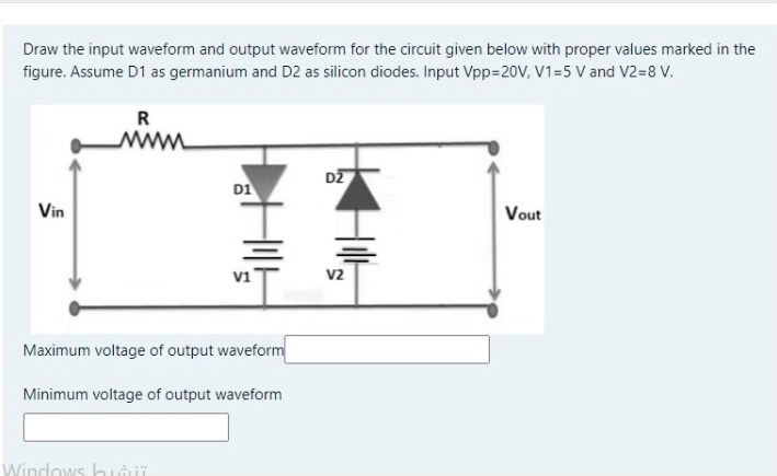

Transcribed Image Text:Draw the input waveform and output waveform for the circuit given below with proper values marked in the
figure. Assume D1 as germanium and D2 as silicon diodes. Input Vpp=20V, V1=5 v and V2=8 V.
R
DZ
D1
Vin
Vout
V2
Maximum voltage of output waveform
Minimum voltage of output waveform
Windows hui
Expert Solution
This question has been solved!
Explore an expertly crafted, step-by-step solution for a thorough understanding of key concepts.

This is a popular solution

Trending nowThis is a popular solution!

Step by stepSolved in 3 steps with 2 images

Knowledge Booster


Learn more about
Need a deep-dive on the concept behind this application? Look no further. Learn more about this topic, electrical-engineering and related others by exploring similar questions and additional content below.Similar questions
- How can you use a zener diode? Please choose one: a. Voltage reference b. both of the above c. constant current source D. none of the abovearrow_forwardR₁ 54 R₂ D₁ ▷ Figure 1: Precision Rectifier 1. Characterize the relationship of input vs. output for the circuit in Figure 1. That is, find an expression for e. You can use the constant voltage drop model for the diodes. VIarrow_forwardhello there can u help for this questionarrow_forward
- If a 75V peak sine wave is applied to a half-wave rectifier, the peak inverse voltage across the diode is?arrow_forwardWhy is the peak inverse voltage of a full rectifier 2Vs - Vo where Vs is the input? What is the purpose of this peak inverse voltage, as in what does it tell me about the diode?arrow_forwardFigure Q1 (a) showed full wave rectifier. The step-down transformer has turn ration 9:1. Cut in voltage for diode is 0.7V, and R₁ = 105 Q. Calculate (i) Output load voltage, Vo. 9:1 A 110V 60Hz B D₁ D. D₂ ↑ D.C. O/Parrow_forward
arrow_back_ios
arrow_forward_ios
Recommended textbooks for you
- Introductory Circuit Analysis (13th Edition)Electrical EngineeringISBN:9780133923605Author:Robert L. BoylestadPublisher:PEARSON
 Delmar's Standard Textbook Of ElectricityElectrical EngineeringISBN:9781337900348Author:Stephen L. HermanPublisher:Cengage Learning
 Programmable Logic ControllersElectrical EngineeringISBN:9780073373843Author:Frank D. PetruzellaPublisher:McGraw-Hill Education
  Fundamentals of Electric CircuitsElectrical EngineeringISBN:9780078028229Author:Charles K Alexander, Matthew SadikuPublisher:McGraw-Hill Education
 Electric Circuits. (11th Edition)Electrical EngineeringISBN:9780134746968Author:James W. Nilsson, Susan RiedelPublisher:PEARSON
 Engineering ElectromagneticsElectrical EngineeringISBN:9780078028151Author:Hayt, William H. (william Hart), Jr, BUCK, John A.Publisher:Mcgraw-hill Education,
Introductory Circuit Analysis (13th Edition)
Electrical Engineering
ISBN:9780133923605
Author:Robert L. Boylestad
Publisher:PEARSON
Delmar's Standard Textbook Of Electricity
Electrical Engineering
ISBN:9781337900348
Author:Stephen L. Herman
Publisher:Cengage Learning
Programmable Logic Controllers
Electrical Engineering
ISBN:9780073373843
Author:Frank D. Petruzella
Publisher:McGraw-Hill Education
Fundamentals of Electric Circuits
Electrical Engineering
ISBN:9780078028229
Author:Charles K Alexander, Matthew Sadiku
Publisher:McGraw-Hill Education
Electric Circuits. (11th Edition)
Electrical Engineering
ISBN:9780134746968
Author:James W. Nilsson, Susan Riedel
Publisher:PEARSON
Engineering Electromagnetics
Electrical Engineering
ISBN:9780078028151
Author:Hayt, William H. (william Hart), Jr, BUCK, John A.
Publisher:Mcgraw-hill Education,