Computer Networking: A Top-Down Approach (7th Edition)
7th Edition
ISBN: 9780133594140
Author: James Kurose, Keith Ross
Publisher: PEARSON
expand_more
expand_more
format_list_bulleted
Question
Draw a Moore machine for a 1965 Ford Thunderbird, a car that featured sequentially flashing tail lights. Define the inputs/outputs of the circuit and draw a state diagram. (There should be 12 states).
As soon as possible!

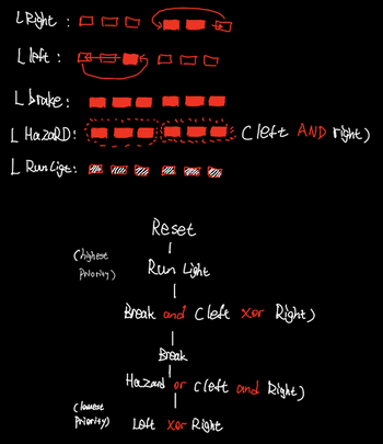
Transcribed Image Text:| Right:0
[left:
L brake:
L HazaRD!
| Run Ligt: We Un Wu Wu
Chighest
Reset
I
Run Light
[
Break and Clefe xor Right)
I
Break
Hazard or cleft and Right)
|
Loft Xor Right
Priority)
(lamest
Priority)
Cleft AND right)
Expert Solution
This question has been solved!
Explore an expertly crafted, step-by-step solution for a thorough understanding of key concepts.
This is a popular solution
Trending nowThis is a popular solution!
Step by stepSolved in 2 steps with 1 images

Follow-up Questions
Read through expert solutions to related follow-up questions below.
Follow-up Question
Draw a Moore machine for a 1965 Ford Thunderbird, a car that featured sequentially flashing tail lights. (There should be 12 states).
As soon as possible!

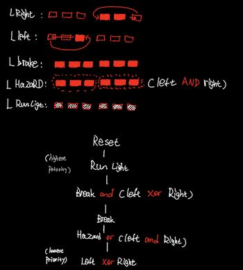
Transcribed Image Text:**Vehicle Light Control System**
This diagram illustrates the functional hierarchy and behavior of a vehicle's light control system. Each light's operation is visually represented and systematically explained with different conditions, indicating how and when the lights are activated based on various input signals.
**Light Signal Representation:**
1. **Right Turn Signal (L Right):**
- Depicted as a series of alternating boxes indicating the blinking pattern.
- Activation indicated by a filled box.
2. **Left Turn Signal (L Left):**
- Similarly shown as a series of alternating boxes for the blinking pattern.
- Activation indicated by a filled box.
3. **Brake Light (L Brake):**
- Shown as a series of consecutive filled boxes.
4. **Hazard Light (L HazARD):**
- Indicated by the sets of filled boxes, merged with conditions that involve both left and right lights (caption: C Left AND Right).
5. **Running Light (L Run Lite):**
- Shaded boxes indicating a continuous activated state when the running lights are on.
**Functional Priority Tree Diagram:**
This hierarchical flowchart depicts the operational priority of different lights:
- **Reset:**
- Initial state.
- **Run Light:**
- First priority, enabling basic running lights.
- **Brake and (Left XOR Right):**
- In the presence of a brake signal along with either a left or right signal.
- **Brake:**
- Showing the condition when only the brake light is activated.
- **Hazard or (Left AND Right):**
- Indicates the hazard light activation or both turn signals simultaneously (hazard condition).
- **Left XOR Right:**
- The condition for activating either the left or right turn signal as separate entities.
Each of these states and conditions is connected via logical operations (AND, OR, XOR), representing the decision-making procedure of the vehicle's light management system where the hierarchy ensures that more critical signals like braking override less critical signals such as turn signals.
Solution
by Bartleby Expert
Follow-up Questions
Read through expert solutions to related follow-up questions below.
Follow-up Question
Draw a Moore machine for a 1965 Ford Thunderbird, a car that featured sequentially flashing tail lights. (There should be 12 states).
As soon as possible!

Transcribed Image Text:**Vehicle Light Control System**
This diagram illustrates the functional hierarchy and behavior of a vehicle's light control system. Each light's operation is visually represented and systematically explained with different conditions, indicating how and when the lights are activated based on various input signals.
**Light Signal Representation:**
1. **Right Turn Signal (L Right):**
- Depicted as a series of alternating boxes indicating the blinking pattern.
- Activation indicated by a filled box.
2. **Left Turn Signal (L Left):**
- Similarly shown as a series of alternating boxes for the blinking pattern.
- Activation indicated by a filled box.
3. **Brake Light (L Brake):**
- Shown as a series of consecutive filled boxes.
4. **Hazard Light (L HazARD):**
- Indicated by the sets of filled boxes, merged with conditions that involve both left and right lights (caption: C Left AND Right).
5. **Running Light (L Run Lite):**
- Shaded boxes indicating a continuous activated state when the running lights are on.
**Functional Priority Tree Diagram:**
This hierarchical flowchart depicts the operational priority of different lights:
- **Reset:**
- Initial state.
- **Run Light:**
- First priority, enabling basic running lights.
- **Brake and (Left XOR Right):**
- In the presence of a brake signal along with either a left or right signal.
- **Brake:**
- Showing the condition when only the brake light is activated.
- **Hazard or (Left AND Right):**
- Indicates the hazard light activation or both turn signals simultaneously (hazard condition).
- **Left XOR Right:**
- The condition for activating either the left or right turn signal as separate entities.
Each of these states and conditions is connected via logical operations (AND, OR, XOR), representing the decision-making procedure of the vehicle's light management system where the hierarchy ensures that more critical signals like braking override less critical signals such as turn signals.
Solution
by Bartleby Expert
Knowledge Booster
Similar questions
- 5. Consider the following description of a finite-state machine. The single external input is X; the single output is Y. Design the sequential circuit using J-K flip-flops Present State Next State Input X 0 0 0 0 1 1 1 1 9.0. 00 01 10 11 00 01 10 1 1 99 10 01 11 10 11 00 00 01 Output Y 0 0 0 1 0 0 للطباعة والاستنساخarrow_forwardNOTE: Provide this question's answer in as much DETAIL as possible. I mean, please answer elaborately!! Please give it both nicely & clearly. Thank you so much sir!!arrow_forward1- In the following sequential circuit. There are 2 D FF (A and B), 2 inputs (x and y), and 1 output z The output and next-states equations are given A(t+1) = x'y + xA B(t+1) = x'B + xA z=B b- List the state table for the sequential circuit.arrow_forward
Recommended textbooks for you
 Computer Networking: A Top-Down Approach (7th Edi...Computer EngineeringISBN:9780133594140Author:James Kurose, Keith RossPublisher:PEARSON
 Computer Organization and Design MIPS Edition, Fi...Computer EngineeringISBN:9780124077263Author:David A. Patterson, John L. HennessyPublisher:Elsevier Science
 Network+ Guide to Networks (MindTap Course List)Computer EngineeringISBN:9781337569330Author:Jill West, Tamara Dean, Jean AndrewsPublisher:Cengage Learning
 Concepts of Database ManagementComputer EngineeringISBN:9781337093422Author:Joy L. Starks, Philip J. Pratt, Mary Z. LastPublisher:Cengage Learning
 Prelude to ProgrammingComputer EngineeringISBN:9780133750423Author:VENIT, StewartPublisher:Pearson Education
 Sc Business Data Communications and Networking, T...Computer EngineeringISBN:9781119368830Author:FITZGERALDPublisher:WILEY

Computer Networking: A Top-Down Approach (7th Edi...
Computer Engineering
ISBN:9780133594140
Author:James Kurose, Keith Ross
Publisher:PEARSON

Computer Organization and Design MIPS Edition, Fi...
Computer Engineering
ISBN:9780124077263
Author:David A. Patterson, John L. Hennessy
Publisher:Elsevier Science

Network+ Guide to Networks (MindTap Course List)
Computer Engineering
ISBN:9781337569330
Author:Jill West, Tamara Dean, Jean Andrews
Publisher:Cengage Learning

Concepts of Database Management
Computer Engineering
ISBN:9781337093422
Author:Joy L. Starks, Philip J. Pratt, Mary Z. Last
Publisher:Cengage Learning

Prelude to Programming
Computer Engineering
ISBN:9780133750423
Author:VENIT, Stewart
Publisher:Pearson Education

Sc Business Data Communications and Networking, T...
Computer Engineering
ISBN:9781119368830
Author:FITZGERALD
Publisher:WILEY