Introductory Circuit Analysis (13th Edition)
13th Edition
ISBN: 9780133923605
Author: Robert L. Boylestad
Publisher: PEARSON
expand_more
expand_more
format_list_bulleted
Question
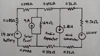
Draw a full circuit diagram of the system described above, correctly annotating all circuit components with the values you have been emailed. Where possible, simplify and redraw the diagram by combining series and parallel resistances

Transcribed Image Text:0.048L
0.272A
0.32.
hean
0.08503
9A
31642
4.70L
2.80A
Radio
20.10V
14.20V(*
Battery
Wind
Generator
Solar
Repeator
Panel
0.048A
0.2721
0.32n
Expert Solution
This question has been solved!
Explore an expertly crafted, step-by-step solution for a thorough understanding of key concepts.
Step by stepSolved in 3 steps with 2 images

Knowledge Booster
Learn more about
Need a deep-dive on the concept behind this application? Look no further. Learn more about this topic, electrical-engineering and related others by exploring similar questions and additional content below.Similar questions
- Needs Complete solution with 100 % accuracy.arrow_forwardYou are the building engineer on the job. The building manager has asked you to install some lighting. The electrical blue print shows that eight 550-W lamps are to be installed on the same circuit. The circuit voltage is 277 volts and is protected by a 20- amp breaker. A continuous-use circuit can be loaded to only 80% of its rating. Is a 20-Amp circuit large enough to carry this load? Explain your answer.arrow_forwardcan someone help me with this problem and explain the concepts step by steparrow_forward
- After completing GVLOER module - Energy use and Energy sources, and further researching your specific type of renewable energy (Geothermal Energy). 1. Define Geothermal Energy 2. Why is it important? 3.How does it work, and why should we care for Geothermal Energy? 4.What are its benefits? 5. How can we protect or preserve Geotheermal Energy? and how environmental friendly it is?arrow_forwardVdc0 U=12 V Circuit #1 Ried V LED www Ried_series 0.05 Vdc0 U = 12 V 0,04 Circuit 0.03 0.02 0.01 RED LED GREEN LE Set current to 10 mA LED voltages Given the circuit #1 presented above, answer the following questions: BLUE_LEC Red 0.5 1) Determine the value of the V₁ (voltage forward of the LED) for the LEDS RED, VDRED GREEN, VREEN and BLUE, VOBLUES when the current through the LEDs is 10mA, 2) Is the LED in Circuit #1, connected in the way that will be lighting up or not - Justify your answer Green 3) Calculate the value of the resistance Rled in Circuit #1, to ensure that a RED LED will have a current of 10 mA 1.5 2 25 Voltage across LED (V) 4) Calculate the value of the resistance Rled in Circuit #1, to ensure that a GREEN LED will have a current of 10 mA Blue 5) Calculate the value of the resistance Rled in Circuit #1, to ensure that a Blue LED will have a current of 10 mA 6) Given three LEDs, connected in series as shown in the Circui # 2 (below), calculate the value of the…arrow_forwardModule 10 Section Review 3.0.0.png Additional Resources Electronics Fundamentals: Circuits, Devices, and Applications, Principles of Electric Circuits, Thomas L. Floyd. New York: Prent 3.0.0 Section Review 1. The letter designation SL on an electrical draw- ing indicates a 4. A a. a. limit switch b. low-voltage switch c. load switch d. light switch b. C. d. 2. Existing power lines on an electrical site plan may be indicated by the letter 5. In t safe a. E b. I a. b. 2 С. Р d. V C. 2 d. 2: 3. The specific types of luminaires required in an installation can be found on the a. power plan b. electrical site plan c. schematic diagram d. lighting fixture schedule P Search for anythingarrow_forward
- Three resistors in parallel: RTotal = 1 R1 1 R2 1 R3 1) The circuit in figure (1) has, Vsupply =40 Volts, R₁ = 300 and R₂= 60 Q. RTotal = a) Calculte the total resistor for this parallel circuit. b) Calculata l₁ and 12, and verfy if |Total =l1 + 12 = c) Calculate the total current for this circuit. Total = Vsupply Figure (1) R₁ R2arrow_forward3. Find the equivalent resistance seen between the indicated nodes, in terms of R. The resistors that are in parallel let them be indicated as ()//() without making the complete calculation. a) Between nodes A and B. b) Between nodes F and G. c) Between nodes B AND E. d) Between nodes D AND F.arrow_forwardI need part Barrow_forward
arrow_back_ios
arrow_forward_ios
Recommended textbooks for you
 Introductory Circuit Analysis (13th Edition)Electrical EngineeringISBN:9780133923605Author:Robert L. BoylestadPublisher:PEARSON
 Delmar's Standard Textbook Of ElectricityElectrical EngineeringISBN:9781337900348Author:Stephen L. HermanPublisher:Cengage Learning
 Programmable Logic ControllersElectrical EngineeringISBN:9780073373843Author:Frank D. PetruzellaPublisher:McGraw-Hill Education
 Fundamentals of Electric CircuitsElectrical EngineeringISBN:9780078028229Author:Charles K Alexander, Matthew SadikuPublisher:McGraw-Hill Education
 Electric Circuits. (11th Edition)Electrical EngineeringISBN:9780134746968Author:James W. Nilsson, Susan RiedelPublisher:PEARSON
 Engineering ElectromagneticsElectrical EngineeringISBN:9780078028151Author:Hayt, William H. (william Hart), Jr, BUCK, John A.Publisher:Mcgraw-hill Education,

Introductory Circuit Analysis (13th Edition)
Electrical Engineering
ISBN:9780133923605
Author:Robert L. Boylestad
Publisher:PEARSON

Delmar's Standard Textbook Of Electricity
Electrical Engineering
ISBN:9781337900348
Author:Stephen L. Herman
Publisher:Cengage Learning

Programmable Logic Controllers
Electrical Engineering
ISBN:9780073373843
Author:Frank D. Petruzella
Publisher:McGraw-Hill Education

Fundamentals of Electric Circuits
Electrical Engineering
ISBN:9780078028229
Author:Charles K Alexander, Matthew Sadiku
Publisher:McGraw-Hill Education

Electric Circuits. (11th Edition)
Electrical Engineering
ISBN:9780134746968
Author:James W. Nilsson, Susan Riedel
Publisher:PEARSON

Engineering Electromagnetics
Electrical Engineering
ISBN:9780078028151
Author:Hayt, William H. (william Hart), Jr, BUCK, John A.
Publisher:Mcgraw-hill Education,