
Introductory Circuit Analysis (13th Edition)
13th Edition
ISBN: 9780133923605
Author: Robert L. Boylestad
Publisher: PEARSON
expand_more
expand_more
format_list_bulleted
Related questions
Question
The schematic is step 7

Transcribed Image Text:**Title: Understanding an RC Circuit with Switches**
**Introduction**
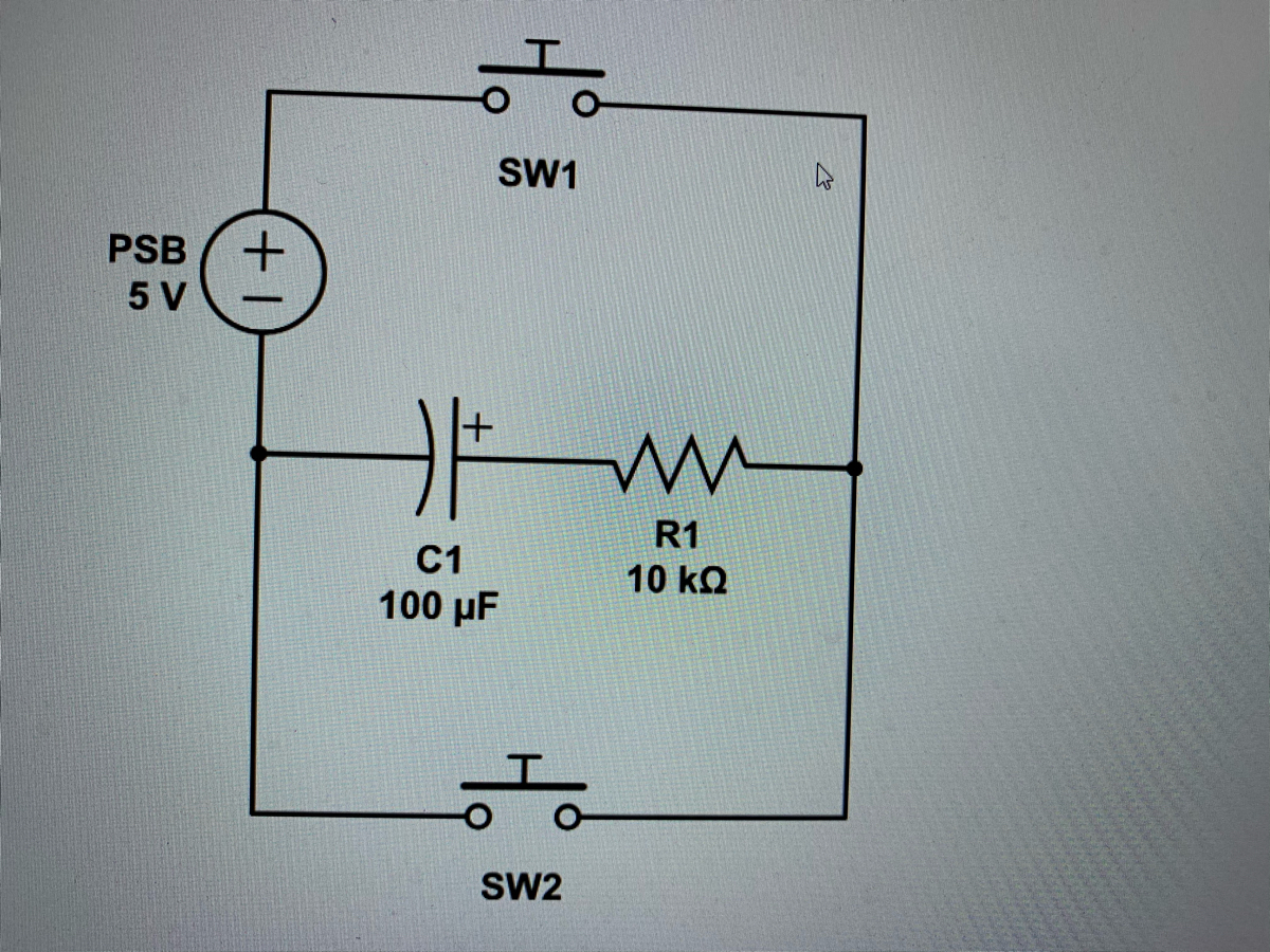
In this educational lesson, we will explore a basic RC (Resistor-Capacitor) circuit. The circuit diagram provided demonstrates the integration of a power supply, capacitor, resistor, and two switches, enabling students to understand the charge and discharge cycles of the capacitor within the circuit.
**Components in the Circuit**
1. **Power Supply (PSB)**: A 5V DC power supply.
2. **Capacitor (C1)**: A 100 µF capacitor.
3. **Resistor (R1)**: A 10 kΩ resistor.
4. **Switches (SW1 and SW2)**: Two switches, SW1 and SW2, are included for controlling the circuit pathways.
**Description of the Circuit Diagram**
- **PSB 5 V**:
- This is the power supply providing a constant voltage of 5V.
- **SW1 and SW2**:
- There are two switches in the circuit, denoted as SW1 and SW2.
- **C1 (100 µF)**:
- This represents a capacitor with a capacitance of 100 microfarads.
- **R1 (10 kΩ)**:
- This represents a resistor with a resistance of 10 kilo-ohms.
**Circuit Operation**
- **Charging Cycle (with SW1 closed)**:
- When switch SW1 is closed and SW2 is open, the circuit allows current to flow from the power supply through the capacitor (C1). The capacitor begins to charge to the voltage provided by the power supply (5V). The charging current is controlled by the resistor (R1), creating a time constant (τ) given by τ = R1 * C1.
- **Discharging Cycle (with SW2 closed)**:
- When switch SW2 is closed and SW1 is open, the path allows the capacitor to discharge through the resistor R1. The discharge will follow an exponential decay until the voltage across the capacitor reaches zero or very close to zero, depending on the time constant (τ = R1 * C1).
**Time Constant (τ)**
- The time constant (τ) is the product of the resistance (R) and capacitance (C) in the circuit:
τ = R1 * C1
τ = 10 kΩ * 100 µF
τ = 10

Transcribed Image Text:### Understanding the Consequences of Closing SW1 and SW2 Together
In electrical engineering, certain configurations can lead to various outcomes on your circuit board. One such scenario is when both SW1 and SW2 are closed at the same time. Understanding the consequences is crucial for troubleshooting and safe circuit design.
Here are the possible outcomes:
1. **Short Circuit Across the PSB**:
- **Explanation**: This would create a short circuit across the power supply bus (PSB). This can cause the power LED on the PSB to go out and potentially damage the voltage regulator if the connection remains over an extended period.
- **Consideration**: This scenario underscores the importance of ensuring that circuit connections are made properly to avoid damaging components.
2. **Rapid Charge and Discharge of the Capacitor**:
- **Explanation**: The capacitor will charge and discharge quickly and repeatedly without any LEDs in series on either the charge path or the discharge path.
- **Observation**: This behavior is typically not desirable as it can lead to erratic behavior and potential overheating.
3. **Charge Neutralization**:
- **Explanation**: The paths with equal and opposite charges will cancel each other out, similar to the neutralization observed in a Leyden Jar, an early type of capacitor.
- **Safety Note**: An important precaution is to avoid receiving an electric shock during this neutralization process, as it can be unpleasant or dangerous.
4. **Simultaneous Charge and Discharge**:
- **Explanation**: The capacitor might both charge and discharge simultaneously. Evidence of this process can be observed by measuring the current through both the charging path and the discharging path.
- **Insight**: This scenario highlights the complex behavior of circuits where components can have multiple states of operation concurrently.
Understanding these outcomes helps in designing safer and more reliable electronic circuits. Proper handling of switches and capacitors ensures efficient operation and prevents damage to components.
Expert Solution
This question has been solved!
Explore an expertly crafted, step-by-step solution for a thorough understanding of key concepts.

Step by stepSolved in 2 steps with 2 images

Knowledge Booster


Learn more about
Need a deep-dive on the concept behind this application? Look no further. Learn more about this topic, electrical-engineering and related others by exploring similar questions and additional content below.Similar questions
- In parallel circuit, the current is Group of answer choices A Less powerful B Unequal C Equal D More powerfularrow_forwardIn the circuit shown below, the current flows through the 69 resistor, I6 is 2A. Find the source current Is. 9Ω www Is www 18Ω 1202 8Ω 602arrow_forwardFor the following circuit answer the question bellow: a b ve c darrow_forward
- B-5-8.Referring to the system shown in Figure 5-75, determine the values of K and K such that the system has a damping ratio of 0.7 and an undamped natural frequency of 4 rad/sec. Figure 5-75 Closed-loop system. R(s) K S +2 k S C(s)arrow_forwardSketch the Y output waveform. So 3. Select inputs S2 W AMA Enable wwwww Do D1 D2 D3 Data inputs D4 D5 D6 D7 FIGURE 6-81arrow_forwardWhat will be the voltage gain for the given circuit?arrow_forward
- 2. Make a schematic diagram of the circuit given below 2.233 AA OFF COM R1 O . o OO R4 R5 R2arrow_forwardAssume that RL = 1K Ohm in the loaded voltage divider shown below. Calculate the output voltage across the load resistor from point B to point C using the loaded voltage divider equation. A R1 2k Ohm .9 V R2 RL 1k Ohm 1.8 V 2 V 8V 7.2 Varrow_forwardAn R-L series circuit contains two resistors and two inductors. The resistors are 86 kΩ and 68 kΩ. the inductors have and inductive reactances of 24 kΩ and 56 kΩ. The total voltage is 480V. What is the voltage drop across the 56 kΩ inductor?arrow_forward
arrow_back_ios
arrow_forward_ios
Recommended textbooks for you
- Introductory Circuit Analysis (13th Edition)Electrical EngineeringISBN:9780133923605Author:Robert L. BoylestadPublisher:PEARSON
 Delmar's Standard Textbook Of ElectricityElectrical EngineeringISBN:9781337900348Author:Stephen L. HermanPublisher:Cengage Learning
 Programmable Logic ControllersElectrical EngineeringISBN:9780073373843Author:Frank D. PetruzellaPublisher:McGraw-Hill Education
  Fundamentals of Electric CircuitsElectrical EngineeringISBN:9780078028229Author:Charles K Alexander, Matthew SadikuPublisher:McGraw-Hill Education
 Electric Circuits. (11th Edition)Electrical EngineeringISBN:9780134746968Author:James W. Nilsson, Susan RiedelPublisher:PEARSON
 Engineering ElectromagneticsElectrical EngineeringISBN:9780078028151Author:Hayt, William H. (william Hart), Jr, BUCK, John A.Publisher:Mcgraw-hill Education,
Introductory Circuit Analysis (13th Edition)
Electrical Engineering
ISBN:9780133923605
Author:Robert L. Boylestad
Publisher:PEARSON
Delmar's Standard Textbook Of Electricity
Electrical Engineering
ISBN:9781337900348
Author:Stephen L. Herman
Publisher:Cengage Learning
Programmable Logic Controllers
Electrical Engineering
ISBN:9780073373843
Author:Frank D. Petruzella
Publisher:McGraw-Hill Education
Fundamentals of Electric Circuits
Electrical Engineering
ISBN:9780078028229
Author:Charles K Alexander, Matthew Sadiku
Publisher:McGraw-Hill Education
Electric Circuits. (11th Edition)
Electrical Engineering
ISBN:9780134746968
Author:James W. Nilsson, Susan Riedel
Publisher:PEARSON
Engineering Electromagnetics
Electrical Engineering
ISBN:9780078028151
Author:Hayt, William H. (william Hart), Jr, BUCK, John A.
Publisher:Mcgraw-hill Education,