Elements Of Electromagnetics
7th Edition
ISBN: 9780190698614
Author: Sadiku, Matthew N. O.
Publisher: Oxford University Press
expand_more
expand_more
format_list_bulleted
Concept explainers
Question
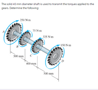
a. Determine the maximum shear stress at segment AB (in MPa)
b. Determine the maximum shear stress at segment BC (in MPa)
c. Determine the maximum shear stress at segment CD (in MPa)
d. Determine the angle twist of Gear D relative to A (in degrees)
note : indicate free body diagram

Transcribed Image Text:The solid 40 mm diameter shaft is used to transmit the torques applied to the
gears. Determine the following:
- 250 N-m
75 N-m
_325 N-m
в
- 150 N-m
500 mm
400 mm
500 mm
Expert Solution
This question has been solved!
Explore an expertly crafted, step-by-step solution for a thorough understanding of key concepts.
This is a popular solution
Trending nowThis is a popular solution!
Step by stepSolved in 2 steps with 4 images

Knowledge Booster
Learn more about
Need a deep-dive on the concept behind this application? Look no further. Learn more about this topic, mechanical-engineering and related others by exploring similar questions and additional content below.Similar questions
- Please show complete work in handwritten format. Don't use chatgpt,If you use Chatgpt it will get a unhelpful rating for sure.arrow_forwardsupplies a torque of The motor shown in Fig. 500 N· m to shaft BCDE. The torques removed at gears C, D, and E are 100 N m, 150 N•m, and 250 N • m, respec- tively. Determine the torques transmitted by transverse cross sections in intervals BC, CD, and DE of the shaft. Barrow_forwardThe two solid shafts are connected by the gears shown. The motor constantly supplies 20 kW of power at 15 Hz to system at A. The yield shear stress is 140 MPa for shaft (1) and 220 MPa for the shaft (2), and over all factor of safety is 2. a) Find the diameter of both shafts. b) If the modulus of rigidity of shaft (2) G is 77.2 GPa, calculate the relative angle of twist D with respect to C. 30 teeth B (1) 48 teeth Tp 0.8 marrow_forward
- - Once answered correctly will UPVOTE!!arrow_forwardHandwriting not allow pleasearrow_forwardA recurring gear train composed of four sprockets 2, 3, 4, 5, has a value of the train of 1: 4 ½, being all the teeth of the gears of the same pitch. 2 has 40 teeth, 3 has 60 teeth. Find the number of teeth in 4 and 5. If the diametral pitch is 3, find the distance between the centers of the arrows. Answer N4 = 25; N5 = 75; 16.667 inarrow_forward
- Please solve, include the diagrams, and do not copy from other bartleby answers. Handwritten solution is more preferred than typed. A flanged bolt coupling connects two shafts. The bolt circle diameter is 250 mm in which there are 12 bolts. The allowable shear stress is 56 MPa in the shafts and 22 MPa in the bolts. One shaft is hollow with outside diameter of 100 mm, while the other one is solid of diameter 50 mm. Determine the ratio of the outside and inside diameter of the hollow shaft and the bolt diameter so that both shafts and the flanged bolt coupling are having the same strength in torsion.arrow_forwardProblem 2: Consider the two gears mounted on the shaft, as shown. Distances are L1 = 100 mm, L2 = 250 mm, and L3 = 175 mm. Diameter of shaft AB is 15 mm, diameter of shaft BC is 20 mm, and diameter of shaft CD is 17.5 mm. Young's modulus for each portion is 200 GPa. Determine the displacement of point D with reference to point A. Also, determine the displacement of point A relative to C. b. Determine the axial strain at any point in shaft segments AB, BC and CD, respectively. If Poisson's ratio for the material of the shafts is v = 0.2, determine the lateral strain in each of the shaft segments. Based on your answers to part (a), do the gears move towards each other, or do they separate from each other? Note that in real gearboxes, movement of gears towards or away from each other is prevented by using thrust bearings. 10 kN 4 kN 5 kN 7 kN 4 kN NY 0I 17.arrow_forwardThe hollow shaft used in the system has the following conditions: Outer Ø:110 mmØ Allowable Shearing Stress:85 MPa Determine the thickness (mm) of the shaft. Round to the nearest whole number for the thickness and use 2 decimal places for other solved values. Provide a torque diagram, strictly follow instructed sign convention, and start from left to right.arrow_forward
arrow_back_ios
arrow_forward_ios
Recommended textbooks for you
 Elements Of ElectromagneticsMechanical EngineeringISBN:9780190698614Author:Sadiku, Matthew N. O.Publisher:Oxford University Press
 Mechanics of Materials (10th Edition)Mechanical EngineeringISBN:9780134319650Author:Russell C. HibbelerPublisher:PEARSON
 Thermodynamics: An Engineering ApproachMechanical EngineeringISBN:9781259822674Author:Yunus A. Cengel Dr., Michael A. BolesPublisher:McGraw-Hill Education
 Control Systems EngineeringMechanical EngineeringISBN:9781118170519Author:Norman S. NisePublisher:WILEY
 Mechanics of Materials (MindTap Course List)Mechanical EngineeringISBN:9781337093347Author:Barry J. Goodno, James M. GerePublisher:Cengage Learning
 Engineering Mechanics: StaticsMechanical EngineeringISBN:9781118807330Author:James L. Meriam, L. G. Kraige, J. N. BoltonPublisher:WILEY

Elements Of Electromagnetics
Mechanical Engineering
ISBN:9780190698614
Author:Sadiku, Matthew N. O.
Publisher:Oxford University Press

Mechanics of Materials (10th Edition)
Mechanical Engineering
ISBN:9780134319650
Author:Russell C. Hibbeler
Publisher:PEARSON

Thermodynamics: An Engineering Approach
Mechanical Engineering
ISBN:9781259822674
Author:Yunus A. Cengel Dr., Michael A. Boles
Publisher:McGraw-Hill Education

Control Systems Engineering
Mechanical Engineering
ISBN:9781118170519
Author:Norman S. Nise
Publisher:WILEY

Mechanics of Materials (MindTap Course List)
Mechanical Engineering
ISBN:9781337093347
Author:Barry J. Goodno, James M. Gere
Publisher:Cengage Learning

Engineering Mechanics: Statics
Mechanical Engineering
ISBN:9781118807330
Author:James L. Meriam, L. G. Kraige, J. N. Bolton
Publisher:WILEY