Elements Of Electromagnetics
7th Edition
ISBN: 9780190698614
Author: Sadiku, Matthew N. O.
Publisher: Oxford University Press
expand_more
expand_more
format_list_bulleted
Concept explainers
Question
thumb_up100%
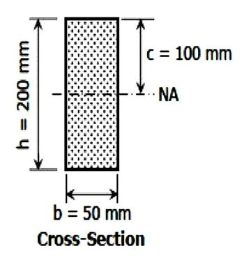
Determine the maximum bending stress in the given figure below.

Transcribed Image Text:200 mm
=
h
b = 50 mm
Cross-Section
c = 100 mm
NA
Expert Solution
This question has been solved!
Explore an expertly crafted, step-by-step solution for a thorough understanding of key concepts.
Step by stepSolved in 2 steps

Knowledge Booster
Learn more about
Need a deep-dive on the concept behind this application? Look no further. Learn more about this topic, mechanical-engineering and related others by exploring similar questions and additional content below.Similar questions
- Q For the beam shown in the figure do the following:- 1. Draw the shear force and bending moment diagrams. 2. Determine the value of the maximum bending moment and its location in the beam. 8 kN/m 4 m 2 marrow_forwardFigure 2 shows a built-up cross-section of a horizontal beam which has a maximum shear force of 100 KN. Calculate the shear stresses and plot the shear stress distribution (Approximate the shear stress at the Neutral axis).arrow_forwardHow do I solve this problem, the numbers I keep getting don't make any sencearrow_forward
- B P = 10 KN L = 2.5 m 1.4 What is the value of the bending moment at x = 1.5 m?arrow_forwardFor the following figure, calculate the shear stress, V, when x = 12.0 m. Draw the Shear Force and Bending Moment diagrams. Remember to correctly place the positive or negative sign and highlight the value of the absolute maximum shear force, the maximum positive and negative bending moments.arrow_forwardA composite beam is made of two brass [E =101 GPa] plates bonded to an aluminum [E =64 GPa] bar, as shown in Figure below. The beam is subjected to a bending moment of 2030 N-m acting about the z axis. Assume b=53 mm, d1=52 mm, d2 =11 mm, Determine: (a)the maximum bending stresses in the brass plates and the aluminum bar. (b) the stress in the brass at the joints where the two materials are bonded together.arrow_forward
- The built-up beam is subjected to a moment of M = 80 kNm. Variable d₁ d₂ d3 da Values for the figure are given in the following table. Note the figure may not be to scale. d5 d3 de d₁ Value 128 mm 22 mm 276 mm 11 mm 138 mm d4 12 mm M₁ de d5 a. Determine the distance from the Neutral Axis to the top of the beam, N.A. b. Determine the mass moment of inertia of the beam, I. Determine the max compressive stress acting on the beam, compression c. d. Determine the max tensile stress acting on the beam, tension.arrow_forwardThe bending moment in a horizontally placed beam at distance x from one of the ends is given by the expression M = 13x - 3x - 12 . The shear force in the beam is zero at, O a. x = 7.12 O b.x = 3 and x = 1.33 O C. X = 2.16 O d. Need more data and a figure to solve the problem.arrow_forwardFor the frame system shown in the figure below, a) Calculate the support reactions. b) Calculate the shear force (V) and bending moment (M) functions using THE METHOD OF SECTIONS. c) Draw the diagrams of those shear force (V) and bending moment (M) functions. Notes: There is a pin support at point A. There is a roller support at point C. (AB - BC) P=8 B w = P kN/m 2 m Carrow_forward
arrow_back_ios
arrow_forward_ios
Recommended textbooks for you
 Elements Of ElectromagneticsMechanical EngineeringISBN:9780190698614Author:Sadiku, Matthew N. O.Publisher:Oxford University Press
 Mechanics of Materials (10th Edition)Mechanical EngineeringISBN:9780134319650Author:Russell C. HibbelerPublisher:PEARSON
 Thermodynamics: An Engineering ApproachMechanical EngineeringISBN:9781259822674Author:Yunus A. Cengel Dr., Michael A. BolesPublisher:McGraw-Hill Education
 Control Systems EngineeringMechanical EngineeringISBN:9781118170519Author:Norman S. NisePublisher:WILEY
 Mechanics of Materials (MindTap Course List)Mechanical EngineeringISBN:9781337093347Author:Barry J. Goodno, James M. GerePublisher:Cengage Learning
 Engineering Mechanics: StaticsMechanical EngineeringISBN:9781118807330Author:James L. Meriam, L. G. Kraige, J. N. BoltonPublisher:WILEY

Elements Of Electromagnetics
Mechanical Engineering
ISBN:9780190698614
Author:Sadiku, Matthew N. O.
Publisher:Oxford University Press

Mechanics of Materials (10th Edition)
Mechanical Engineering
ISBN:9780134319650
Author:Russell C. Hibbeler
Publisher:PEARSON

Thermodynamics: An Engineering Approach
Mechanical Engineering
ISBN:9781259822674
Author:Yunus A. Cengel Dr., Michael A. Boles
Publisher:McGraw-Hill Education

Control Systems Engineering
Mechanical Engineering
ISBN:9781118170519
Author:Norman S. Nise
Publisher:WILEY

Mechanics of Materials (MindTap Course List)
Mechanical Engineering
ISBN:9781337093347
Author:Barry J. Goodno, James M. Gere
Publisher:Cengage Learning

Engineering Mechanics: Statics
Mechanical Engineering
ISBN:9781118807330
Author:James L. Meriam, L. G. Kraige, J. N. Bolton
Publisher:WILEY