
Elements Of Electromagnetics
7th Edition
ISBN: 9780190698614
Author: Sadiku, Matthew N. O.
Publisher: Oxford University Press
expand_more
expand_more
format_list_bulleted
Related questions
Question
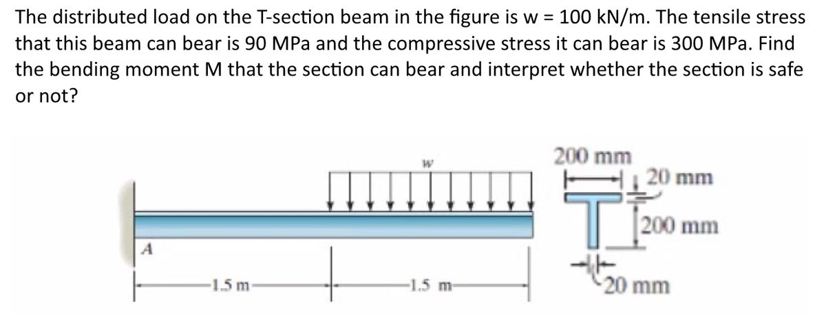

Transcribed Image Text:The distributed load on the T-section beam in the figure is w = 100 kN/m. The tensile stress
that this beam can bear is 90 MPa and the compressive stress it can bear is 300 MPa. Find
the bending moment M that the section can bear and interpret whether the section is safe
or not?
200 mm
20 mm
200 mm
-1.5 m
-1.5 m
20 mm
Expert Solution
This question has been solved!
Explore an expertly crafted, step-by-step solution for a thorough understanding of key concepts.

This is a popular solution

Trending nowThis is a popular solution!

Step by stepSolved in 2 steps with 8 images

Knowledge Booster


Learn more about
Need a deep-dive on the concept behind this application? Look no further. Learn more about this topic, mechanical-engineering and related others by exploring similar questions and additional content below.Similar questions
- consider a beam with two 60-inch-long rods. The rods have a cross section area of 0.50 in 2 . Find the axial stress in each rod, draw the shear and moment diagrams for the beam, and find the maximum stress in the beam.arrow_forwardPlease draw shear force diagram v(X) and bending moment diagram m(X)arrow_forwardFind the shear force and bending moment at points C and D. 500 lb 200 lb A Answer: Vc = -386 lbf Mc = -857 lbf.ft VD = 300 lbf Mp = -600 lbf.ft C² 6 ft4 ft 4 ft B 6 ft D 300 lb 2 ft Earrow_forward
- Find the reactions of the structure and draw the shear and moment diagrams for the beam (Use the Force Method).arrow_forwardA simply supported beam with a length of 4m is loaded with a uniform distributed load (w). The beam has a rectangular hollow section with the following dimensions: Outer Base = 150 mm OuterDepth 200 mm Inner Base = 100 mm Depth = 150 mm Inner Determine the maximum uniformly distributed load which can be applied over the entire length of the beam if the bending stress is limited to 8 Mpa. Please answer with solution and fbd. Thank you.arrow_forwardDraw the shear force and bending moment diagrams for 2 kip the beam under the external loadings shown in the figure. 200 lb/t Note use the graphical method; show all the critical tuming points of each curve, along with the calculation steps used in determining the critical points. 9arrow_forward
- Draw shear force and bending moment diagrams. Indicate sign and peak values of internal forces. Use method of sections showing cuts and equationsarrow_forwardIn figure 1, a curved beam has a solid circular cross-section of 0.10 m in diameter. If a maximum tensile and compressive stress in the member are not to exceed 150 MPa and 200 MPa, respectively, determine the value of the load P that can safely be carried by the member. 1 D = 0.10 m 2 0.15 m 0.05 m R=0.10 m Parrow_forward
arrow_back_ios
arrow_forward_ios
Recommended textbooks for you
- Elements Of ElectromagneticsMechanical EngineeringISBN:9780190698614Author:Sadiku, Matthew N. O.Publisher:Oxford University Press
 Mechanics of Materials (10th Edition)Mechanical EngineeringISBN:9780134319650Author:Russell C. HibbelerPublisher:PEARSON
 Thermodynamics: An Engineering ApproachMechanical EngineeringISBN:9781259822674Author:Yunus A. Cengel Dr., Michael A. BolesPublisher:McGraw-Hill Education
  Control Systems EngineeringMechanical EngineeringISBN:9781118170519Author:Norman S. NisePublisher:WILEY
 Mechanics of Materials (MindTap Course List)Mechanical EngineeringISBN:9781337093347Author:Barry J. Goodno, James M. GerePublisher:Cengage Learning
 Engineering Mechanics: StaticsMechanical EngineeringISBN:9781118807330Author:James L. Meriam, L. G. Kraige, J. N. BoltonPublisher:WILEY
Elements Of Electromagnetics
Mechanical Engineering
ISBN:9780190698614
Author:Sadiku, Matthew N. O.
Publisher:Oxford University Press
Mechanics of Materials (10th Edition)
Mechanical Engineering
ISBN:9780134319650
Author:Russell C. Hibbeler
Publisher:PEARSON
Thermodynamics: An Engineering Approach
Mechanical Engineering
ISBN:9781259822674
Author:Yunus A. Cengel Dr., Michael A. Boles
Publisher:McGraw-Hill Education
Control Systems Engineering
Mechanical Engineering
ISBN:9781118170519
Author:Norman S. Nise
Publisher:WILEY
Mechanics of Materials (MindTap Course List)
Mechanical Engineering
ISBN:9781337093347
Author:Barry J. Goodno, James M. Gere
Publisher:Cengage Learning
Engineering Mechanics: Statics
Mechanical Engineering
ISBN:9781118807330
Author:James L. Meriam, L. G. Kraige, J. N. Bolton
Publisher:WILEY