Introductory Circuit Analysis (13th Edition)
13th Edition
ISBN: 9780133923605
Author: Robert L. Boylestad
Publisher: PEARSON
expand_more
expand_more
format_list_bulleted
Question

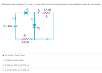
Transcribed Image Text:Determine the currents 1, 12 and 13 respectively for the network shown. Use simplified model for the diodes.
D
3.3 k2
R2
E = 20V
D2
R1
5.6 kN
10.52 mA, 17 mA, 20mA
1.004 mA, OmA, 7.44 A
O 0.514 mA, 2.62 mA, 0.799 mA
O 3.32 mA, 0.212 mA, 3.108 mA
Expert Solution
This question has been solved!
Explore an expertly crafted, step-by-step solution for a thorough understanding of key concepts.
Step by stepSolved in 2 steps with 1 images

Knowledge Booster
Learn more about
Need a deep-dive on the concept behind this application? Look no further. Learn more about this topic, electrical-engineering and related others by exploring similar questions and additional content below.Similar questions
- A half wave rectifier circuit with a 1K ohm load operates from a 120V rms 60-Hz household supply through a 10-to-1 step down transformer. It uses a silicon diode that can be modeled to have a 0.7V drop for any current. What is the peak voltage of the rectified output? For what fraction of a cycle does the diode conduct? What is the average output voltage? What is the average current in the load? Thanks for any help.arrow_forward5. A voltage source produces a "Triangle" wave and is connected to a series diode and resistor circuit as shown. D1 KH D V1 #1 V R1 R Using the nominal piecewise linear model for a diode, determine from the following possibilities the graph that best represents the voltage across the resistor? (Delete those that do not apply) (Blue curve VR, dashed curve V1). Then determine which graph best represents the voltage across the diode.arrow_forward3-phase-demos-3vi File Edit View Project Operate Tools Window Help Waveform Chart 8 21 2- 18- 16- 14- 12- 1- 08- 06 04- 02- 0 -02- 04- -06- 08- -1- -12- 14- Time རྔ་ལྷ་ལྟ་ Amplitude Time A-B (D1, DS) A-C (D1, D6) B-C (D2, D6) B-A (D2, D4) C-A (D3 D4) C-B (D3, D5) A-B A-CA B-C B-A C-A C-B KKKKKK 081 -0.92 -1.73 081 0.92 1.73arrow_forward
- Consider two reverse biased diodes. If the ratio of applied reverse bias voltages is 0.5, find the ratio of transition capacitances of the two diodes.arrow_forwardDetermine the điode's voltoge ond current for Hhe figure the diode's model. Find the volItage for each of Si 20 across the resistor in each case. Find the diode's power also In each case A ssume Rg is lo r.arrow_forwarduse a P-N junction ideal diode to simulate a circuit measure and plot its I-V characteristics as well as its forward characteristics. assume breakdown voltage of around 6V for your calculations. I have added my multisim design with IV graph of the diode. I need : the large signal piece wise linear parameters of the diode. and for the plot do the theoretical calculations for at least one point on the curve and mark it on the curve This peoblem has other part that I will send when the expert answered this part. Tnxarrow_forward
- Choose the doping material that will cause silicon to become a p-type semiconductor. A. Ge B. As C. Te D. Barrow_forwardConsider two reverse biased diodes. If the ratio of applied reverse bias voltages is 0.5, find the ratio of transition capacitances of the two diodes.arrow_forwardFor the diode circuit to the right 8002 a V 1002 b 40mA 0.001V' a) To the left of points a and b, find the load-line relation by expressing the current, I with voltage, V. HINT: Write KCL equation for the circuit diagram and write I in terms of V from that KCL equation. This will be your load-line equation. b) Assume the diode has the following characteristic, using the load-line relation you found in (a), determine the operating voltage, V and current, I for the circuit. ip (mA) 20 15 10 5 Vp (V) 3.0 0.5 '1.0 1.5 2.0 2.5arrow_forward
- Please solve i Give upvotearrow_forwardA DA Vm sin cor For the following single-phase full-wave diode rectifier, Vm = 311 V, R = 1 N, L = 0.002 H and the source frequency is given as 50 Hz. Welding current Find the THD. Note: You can consider calculating the effective value of the welding current and the effective value of the fundamental wave of the welding current. wwarrow_forward
arrow_back_ios
arrow_forward_ios
Recommended textbooks for you
 Introductory Circuit Analysis (13th Edition)Electrical EngineeringISBN:9780133923605Author:Robert L. BoylestadPublisher:PEARSON
 Delmar's Standard Textbook Of ElectricityElectrical EngineeringISBN:9781337900348Author:Stephen L. HermanPublisher:Cengage Learning
 Programmable Logic ControllersElectrical EngineeringISBN:9780073373843Author:Frank D. PetruzellaPublisher:McGraw-Hill Education
 Fundamentals of Electric CircuitsElectrical EngineeringISBN:9780078028229Author:Charles K Alexander, Matthew SadikuPublisher:McGraw-Hill Education
 Electric Circuits. (11th Edition)Electrical EngineeringISBN:9780134746968Author:James W. Nilsson, Susan RiedelPublisher:PEARSON
 Engineering ElectromagneticsElectrical EngineeringISBN:9780078028151Author:Hayt, William H. (william Hart), Jr, BUCK, John A.Publisher:Mcgraw-hill Education,

Introductory Circuit Analysis (13th Edition)
Electrical Engineering
ISBN:9780133923605
Author:Robert L. Boylestad
Publisher:PEARSON

Delmar's Standard Textbook Of Electricity
Electrical Engineering
ISBN:9781337900348
Author:Stephen L. Herman
Publisher:Cengage Learning

Programmable Logic Controllers
Electrical Engineering
ISBN:9780073373843
Author:Frank D. Petruzella
Publisher:McGraw-Hill Education

Fundamentals of Electric Circuits
Electrical Engineering
ISBN:9780078028229
Author:Charles K Alexander, Matthew Sadiku
Publisher:McGraw-Hill Education

Electric Circuits. (11th Edition)
Electrical Engineering
ISBN:9780134746968
Author:James W. Nilsson, Susan Riedel
Publisher:PEARSON

Engineering Electromagnetics
Electrical Engineering
ISBN:9780078028151
Author:Hayt, William H. (william Hart), Jr, BUCK, John A.
Publisher:Mcgraw-hill Education,