Structural Analysis
6th Edition
ISBN: 9781337630931
Author: KASSIMALI, Aslam.
Publisher: Cengage,
expand_more
expand_more
format_list_bulleted
Question
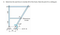
Determine the axial forces in members dg and be of the frame. note the joint D is a sliding pin

Transcribed Image Text:4. Determine the axial force in member BC of the frame. Note the joint Dis a sliding pin.
B
D
Dimensions
in mm
60
16 N-m
70
Expert Solution
This question has been solved!
Explore an expertly crafted, step-by-step solution for a thorough understanding of key concepts.
This is a popular solution
Trending nowThis is a popular solution!
Step by stepSolved in 4 steps with 5 images

Knowledge Booster
Similar questions
- Find the force in member EF. Use Method of Joints.arrow_forwardSolve for the force in all members of the truss. Show solutions. 0.8m 2.6m A 13N 3m 1m 12KN B 1m E 12KN 8KN 3.6m 1m F 2.6m 6KN Sarrow_forwardThe truss shown is designed to support a staircase. For all questions, indicate whether the members are in tension or compression. Assume that all joints are pinned. Use the method of sections for each part.a. Determine the force in members EG, FG, and HFb. Determine the force in members EF and DFarrow_forward
- Given the following truss, determine: a. The external reactions of the truss (Ray, Rcx, Rcy). b. The internal forces in all elements (tension or compression), applying the method of nodes.c. Draw the proposed truss, identifying which elements are in tension and which are in compression.arrow_forwardDetermine the force in member BE of the loaded truss. The force is positive if in tension, negative if in compression. 6 kN 2 m C 6 kN E 2 m B 7 kN 2 m A 4 marrow_forwardDetermine the forces in members AB, BI, and CI of the simple truss. Note that all curved members are two-force members. The forces are positive if in tension, negative if in compression. Arc of radius 44.0 m H B C D YL E YL 14 m 14 m 19 m 14 m 14 m 21 m Farrow_forward
- The members of the truss are assumed to be pinconnected. If member CB is an A-36 steel rod of 40 mmdiameter, determine the maximum load P that can besupported by the truss without causing the member tobuckle. For A36 steel E=200 GPa and σY = 250 Mpaarrow_forwardFor the given truss a. Draw the free-body diagram without the zero-force members. b. Use the method of sections to find the forces in members RS, MG, and ER. Assume that member ER carries twice the magnitude of the force carried by the member DE. c. Use the method of joints to find the forces in members VW and OW. Indicate whether the forces are in tension or in compression. 5 kN 2 kN B D 50° G E 0.5 m 0.5 m R T 0.25 m 30° 3 KN X. 0.5 m 4 kN 0.6 m 1.2 m 1.2 m 1.2 m 1.2 m 1.2 marrow_forward5arrow_forward
arrow_back_ios
arrow_forward_ios
Recommended textbooks for you

 Structural Analysis (10th Edition)Civil EngineeringISBN:9780134610672Author:Russell C. HibbelerPublisher:PEARSON
 Principles of Foundation Engineering (MindTap Cou...Civil EngineeringISBN:9781337705028Author:Braja M. Das, Nagaratnam SivakuganPublisher:Cengage Learning
 Fundamentals of Structural AnalysisCivil EngineeringISBN:9780073398006Author:Kenneth M. Leet Emeritus, Chia-Ming Uang, Joel LanningPublisher:McGraw-Hill Education
 Traffic and Highway EngineeringCivil EngineeringISBN:9781305156241Author:Garber, Nicholas J.Publisher:Cengage Learning


Structural Analysis (10th Edition)
Civil Engineering
ISBN:9780134610672
Author:Russell C. Hibbeler
Publisher:PEARSON

Principles of Foundation Engineering (MindTap Cou...
Civil Engineering
ISBN:9781337705028
Author:Braja M. Das, Nagaratnam Sivakugan
Publisher:Cengage Learning

Fundamentals of Structural Analysis
Civil Engineering
ISBN:9780073398006
Author:Kenneth M. Leet Emeritus, Chia-Ming Uang, Joel Lanning
Publisher:McGraw-Hill Education


Traffic and Highway Engineering
Civil Engineering
ISBN:9781305156241
Author:Garber, Nicholas J.
Publisher:Cengage Learning