Elements Of Electromagnetics
7th Edition
ISBN: 9780190698614
Author: Sadiku, Matthew N. O.
Publisher: Oxford University Press
expand_more
expand_more
format_list_bulleted
Question
Please help solving. Thank you

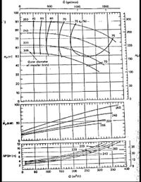
Transcribed Image Text:O (gal/min)
500
1000
1500
100
260
40
50
60
70
300
90
75 n1%) -
80
240
250
75
70
220
200
60
205
Hefm) 50
Hp
150
Outer diameter
of impeller (rnm)
70
40
100
30
20
10
100
260
240
220
"ptkW} 50
205
12
205 *
220
30
10
260
240
20
NPSH (m) 6
10
0.
400
100
160
200
250
300
360
50
a (m/h)

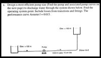
Transcribed Image Text:c. Design a most efficient pump size (Find the pump and associated pump curves on
the next page) to discharge water through the system shown below. Find the
operating system point. Include losses from transitions and fittings. The
performance curve Assume f = 0.015.
Elev. = 160 m
Elev. = 100 m
Pump
Elbow r/d=2
1000-m pipe; 10 cm dia.
Expert Solution
This question has been solved!
Explore an expertly crafted, step-by-step solution for a thorough understanding of key concepts.
Step by stepSolved in 3 steps

Knowledge Booster
Learn more about
Need a deep-dive on the concept behind this application? Look no further. Learn more about this topic, mechanical-engineering and related others by exploring similar questions and additional content below.Similar questions
- Please don't copy from other site.arrow_forwardThe pump shown on the figure below has characteristic curves shown in the graph. Estimate the flow rate and, a) Calculate the pump power requirement b) Calculate the pressure at the pump inlet & outlet c) Sketch the EGL & HGL Water 10°C € 20 m 16-cm-dia. wrought iron pipe 10 m I 10 m 30 m 8 m 10 m Water 20°C Hp (m) 80 60 40 20 Hp 0.1 0.2 Q (m³/s) 0.3 ПР 80 60 40 20 ПРarrow_forwardMECHANICS OF FLUIDS (I)arrow_forward
- 1 QUESTION 1 Consider a desired pump operating condition which adds 35 psi at a flowrate of 500 gpm to water (p= 62 11m/ft²³) Ignore any changes in Kinetic or potential energy and Tassume isothermal flow C.e. internal energy is constant, this is the normal assumption we make when analyzing fluid flows in piping systems). Apply the energy balance only across the pump with full energy Balance and simlifying to solve for the pump, Starting head symbolically. Then begin careful of units, Solve for pump head in feet. GIVEN: 35psi 500 gpm p=62 1bm/3 XA. 10.5 A B. 100.8 ft C. 50.1 ft D. 80.7f 35 500 62 (32.2) + 2(32.2) 35 + 500arrow_forward02 h, are 12m. The pump efficiency is 79%, and the pump is driven by an electric motor. A pump moves water @10°C from a lake into a large, pressurized holding tank as shown. The flow rate, Q. is 375 L/min, and the piping system losses, 1) Sketch the setup (simple schematic is good), 2) label the z datum, and 3) identify and label the boundary conditions (P, V, and z) at 1 and 2 for use in a) the General Energy Equation (GEE). Provide values and units for the boundary conditions. Hint: For identifying good locations for boundary conditions, where are the velocities approximately zero? b) Calculate the head added to the fluid, h,, by the pump. Give your answer in units of m. Hint: Be careful with signs in manipulating the GEE. Show as many steps as you need to get your h, equation correct. Calculate the power added to the fluid by the pump in units of kW. () Determine the required electric motor size to drive the pump in units of HP. Prank = 200 kPa Holding Tank Air 6 m Pump Lakearrow_forwardFigure shows two points a half-period apart in theoperation of a pump. What type of pump is this ? Howdoes it work? Sketch your best guess of flow rate versustime for a few cycles.arrow_forward
- A pump delivers water from a tank (A)X water surface elevation-110m) to tank B (water surface elevation= 170m). The suction pipe is 45m long and 35cm in diameter the delivered pipe is 950m long 25cm in diameter. Loss head due to friction hf1 = 5m and h2 3m If the piping are from pipe(1)= steel sheet metal pipe(2)= stainless – steel Calculate the following i) ii) The discharge in the pipeline The power delivered by the pump.arrow_forwardConsider a desired pump operating condition which adds 35 psi at a flow rate of 500 gpa to water. Ignore any changes in Kinetic or potential energy and assume isothermal flow (ie. Internal energy is constant, this is normal assumption we make when analyzing fluid flows in piping systems). Apply the energy balance only across the pump starting with full energy balance and simplifying to solve for the pump head symbolically. Then begin careful of unit, solve for pump head in feet. Given erosion 500 gpm P=62 lbs/ft^3 A- 10.5 ft B- 100.8 ft C- 50.1 ft D-80.7 ftarrow_forwardGive detailed solution,Only Handwritten.arrow_forward
- 10.0 m 200 m 2. An old western town has a water tower to deliver water to the residents. Pictured above is the water tower. The water tower is closed but there is a section of air that is atmospheric pressure just above the water. The corsss ectional area at point 2 is 4.75 x 10 m. The cross sectional area fot the water tower is very large. What is the speed of the water coming out of the pipe at point 2? (density of water = kg/m³) 3. On a vacation trip up in Oregon my boys decided to build a 10 kg raft that they made out of driftwood. 1000arrow_forwardAnswer the following: e.) What is the pump head? f.) Pump horsepower or water powerarrow_forwardPlease answer Problem 10-15 thank youarrow_forward
arrow_back_ios
SEE MORE QUESTIONS
arrow_forward_ios
Recommended textbooks for you
 Elements Of ElectromagneticsMechanical EngineeringISBN:9780190698614Author:Sadiku, Matthew N. O.Publisher:Oxford University Press
 Mechanics of Materials (10th Edition)Mechanical EngineeringISBN:9780134319650Author:Russell C. HibbelerPublisher:PEARSON
 Thermodynamics: An Engineering ApproachMechanical EngineeringISBN:9781259822674Author:Yunus A. Cengel Dr., Michael A. BolesPublisher:McGraw-Hill Education
 Control Systems EngineeringMechanical EngineeringISBN:9781118170519Author:Norman S. NisePublisher:WILEY
 Mechanics of Materials (MindTap Course List)Mechanical EngineeringISBN:9781337093347Author:Barry J. Goodno, James M. GerePublisher:Cengage Learning
 Engineering Mechanics: StaticsMechanical EngineeringISBN:9781118807330Author:James L. Meriam, L. G. Kraige, J. N. BoltonPublisher:WILEY

Elements Of Electromagnetics
Mechanical Engineering
ISBN:9780190698614
Author:Sadiku, Matthew N. O.
Publisher:Oxford University Press

Mechanics of Materials (10th Edition)
Mechanical Engineering
ISBN:9780134319650
Author:Russell C. Hibbeler
Publisher:PEARSON

Thermodynamics: An Engineering Approach
Mechanical Engineering
ISBN:9781259822674
Author:Yunus A. Cengel Dr., Michael A. Boles
Publisher:McGraw-Hill Education

Control Systems Engineering
Mechanical Engineering
ISBN:9781118170519
Author:Norman S. Nise
Publisher:WILEY

Mechanics of Materials (MindTap Course List)
Mechanical Engineering
ISBN:9781337093347
Author:Barry J. Goodno, James M. Gere
Publisher:Cengage Learning

Engineering Mechanics: Statics
Mechanical Engineering
ISBN:9781118807330
Author:James L. Meriam, L. G. Kraige, J. N. Bolton
Publisher:WILEY