
Introductory Circuit Analysis (13th Edition)
13th Edition
ISBN: 9780133923605
Author: Robert L. Boylestad
Publisher: PEARSON
expand_more
expand_more
format_list_bulleted
Related questions
Question
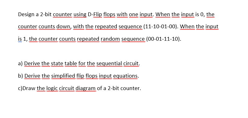

Transcribed Image Text:Design a 2-bit counter using D-Flip flops with one input. When the input is 0, the
ww m wwww
w w m w i
ww ww wwww
www
counter counts down, with the repeated sequence (11-10-01-00). When the input
is 1, the counter counts repeated random sequence (00-01-11-10).
a) Derive the state table for the sequential circuit.
wwwww
b) Derive the simplified flip flops input equations.
www w w
ww www m www ww
c)Draw the logic circuit diagram of a 2-bit counter.
Expert Solution
This question has been solved!
Explore an expertly crafted, step-by-step solution for a thorough understanding of key concepts.

This is a popular solution

Trending nowThis is a popular solution!

Step by stepSolved in 4 steps with 6 images

Knowledge Booster


Learn more about
Need a deep-dive on the concept behind this application? Look no further. Learn more about this topic, electrical-engineering and related others by exploring similar questions and additional content below.Similar questions
- 5. JK flip-flops are often used to build counters. The JK flip-flop will toggle the original output value when triggered by the clock signal if both the J,K inputs are connected with a constant "high"(logic 1). All the JK flip-flops in Figure 2 are negative edge triggered. All the initial values of Q2Q1Q0 are 0. Qo (LSB) (MSB) Input K K Logic 1 Input Q2 000 Figure 2. Counter (a) Sketch the output waveforms forQ2 Q1 Q0. Write down the output binary value (Q2Q1Q0: such as "000", "001") for each clock period on the figure. (b) Describe the function of the counter (e.g. binary down counter counting from 7 to 0).arrow_forwardDraw a Moore-type state diagram and design a synchronous sequential circuit using D flip flops for a 1-input/1-output "sequence detector" for the sequence 11 (be sure to recognize overlapping sequences). Draw the final circuit. Draw a Moore-type state diagram and design a synchronous sequential circuit using D flip flops for a 1-input/1-output "sequence detector" for the sequence 100 (be sure to recognize overlapping sequences). Draw the final circuit. Draw a Moore-type state diagram and design a synchronous sequential circuit using D flip flops for a 1-input/1-output "sequence detector" for the sequence 110 (be sure to recognize overlapping sequences). Draw the final circuit. Draw a Moore-type state diagram and design a synchronous sequential circuit using D flip flops for a 1-input/1-output "sequence detector" for the sequence 000 (be sure to recognize overlapping sequences). Draw the final circuit. Draw a Moore-type state diagram and design a synchronous sequential circuit using D…arrow_forwardplease help just answer as much as you can, no need to complete all. thank youarrow_forward
arrow_back_ios
arrow_forward_ios
Recommended textbooks for you
- Introductory Circuit Analysis (13th Edition)Electrical EngineeringISBN:9780133923605Author:Robert L. BoylestadPublisher:PEARSON
 Delmar's Standard Textbook Of ElectricityElectrical EngineeringISBN:9781337900348Author:Stephen L. HermanPublisher:Cengage Learning
 Programmable Logic ControllersElectrical EngineeringISBN:9780073373843Author:Frank D. PetruzellaPublisher:McGraw-Hill Education
  Fundamentals of Electric CircuitsElectrical EngineeringISBN:9780078028229Author:Charles K Alexander, Matthew SadikuPublisher:McGraw-Hill Education
 Electric Circuits. (11th Edition)Electrical EngineeringISBN:9780134746968Author:James W. Nilsson, Susan RiedelPublisher:PEARSON
 Engineering ElectromagneticsElectrical EngineeringISBN:9780078028151Author:Hayt, William H. (william Hart), Jr, BUCK, John A.Publisher:Mcgraw-hill Education,
Introductory Circuit Analysis (13th Edition)
Electrical Engineering
ISBN:9780133923605
Author:Robert L. Boylestad
Publisher:PEARSON
Delmar's Standard Textbook Of Electricity
Electrical Engineering
ISBN:9781337900348
Author:Stephen L. Herman
Publisher:Cengage Learning
Programmable Logic Controllers
Electrical Engineering
ISBN:9780073373843
Author:Frank D. Petruzella
Publisher:McGraw-Hill Education
Fundamentals of Electric Circuits
Electrical Engineering
ISBN:9780078028229
Author:Charles K Alexander, Matthew Sadiku
Publisher:McGraw-Hill Education
Electric Circuits. (11th Edition)
Electrical Engineering
ISBN:9780134746968
Author:James W. Nilsson, Susan Riedel
Publisher:PEARSON
Engineering Electromagnetics
Electrical Engineering
ISBN:9780078028151
Author:Hayt, William H. (william Hart), Jr, BUCK, John A.
Publisher:Mcgraw-hill Education,