Question

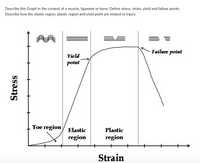
Transcribed Image Text:Describe this Graph in the context of a muscle, ligament or bone. Define stress, strain, yield and failure points.
Describe how the elastic region, plastic region and yield point are related to injury.
Failure point
Yield
point
Тоe region
Elastic
Plastic
region
region
Strain
Stress
Expert Solution
This question has been solved!
Explore an expertly crafted, step-by-step solution for a thorough understanding of key concepts.
This is a popular solution
Trending nowThis is a popular solution!
Step by stepSolved in 3 steps with 3 images

Knowledge Booster
Similar questions
- The beam supports the loading shown. Determine the state of stress at points E and F at section a-a.arrow_forwardThe table shown in the image below shoes the stress and strain values (in MPa) for a silk spider thread. Using the linear part of the curve, calculate the Young’s modulus for the spider silk. (Hint: First plot a stress versus strain curve for the data shown) Title of table is: Stress (MPa) strainarrow_forward7. Carbon steel is tested in uniaxial tension, as shown in the inset schematic, to produce the following stress-strain diagram. 600 500 MPa 600 g 400 400 300 200 200 100 0.005 0.05 0.10 0.15 Strain E Figure 1: Stress vs. strain for plain carbon steel. Note: the inset shows the initial portion of the data, magnified for clarity. a) From the Figure 1, determine the following material properties: (i) elastic modulus, E, (ii) ultimate tensile strength, UTS, (iii) yield stress, oy. b) Label the following regions or points on the figure: (i) fracture point, (ii) plastic region, (iii) elastic region. 8. You wish to design a new bone screw used to hold fractured bone segments together or to hold implants in place. Describe what type of material you would use and what considerations you need to make. 27°F Cloudy Stress (MPa) aarrow_forward
arrow_back_ios
arrow_forward_ios