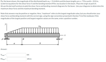
For the beam shown, the magnitude of the distributed load is w0 = 11.6 kN/m and the beam lengths are a = 7.0 m and b = 21.0 m.
(a) derive equations for the shear force V and the bending moment M for any location in the beam. Place the origin at point A.
(b) use the derived functions to plot the shear-force and bending-moment diagrams for the beam. Use your diagrams to determine the maximum shear force and the maximum bending moment.
Note that answers may be positive or negative. Here, "maximum" refers to the largest magnitude value, but you should enter your shear force and bending moment with the correct sign, using the sign convention presented in Section 7.2 of the textbook. If the magnitudes of the largest positive and largest negative values are the same, enter a positive number.

Step by stepSolved in 5 steps with 1 images

- The two sub questions and question g as well :arrow_forwardI need the answer as soon as possiblearrow_forwardSolve the problem by the moment-area method. The beam has constant flexural rigidity EI. A simple beam AB supports two concentrated loads P at the positions shown in the figure. B C 4. 4 A support C at the midpoint of the beam is positioned at distance d below the beam before the loads are applied. Assuming that d = 12 mm, L = 5.4 m, E = 200 GPa, and I = 193 x 10° mm, calculate the magnitude of the loads P (in kN) so that the beam just touches the support at C. 163.87 x kNarrow_forward
- simply supported beam is subjected to a uniform load of 400 lb/ft and a concentrated load of 900 lb as shown in the below figure a. Find the reactions. b. Express the internal shear and moment in terms of x and then draw the shear and moment diagrams for the beam. Label the points of maximum bending on the bending moment diagram. Determine the maximum tensile and compressive stresses due to bending and specify their location. 900 lb =arrow_forwardsub-partarrow_forwardFor the beam and loading shown, (a) Use discontinuity functions to write the expression for w(x). Include the beam reactions in this expression. (b) Integrate w(x) twice to determine V(x) and M(x). (c) Use V(x) and M(x) to plot the shear-force and bending-moment diagrams. Let a = 3.0 m, b = 1 m, WA = 18 kN/m, and wg = 45 kN/m. Label all significant points on each diagram and identify the maximum shear force and bending moment along with their respective locations. Clearly differentiate straight-line and curved portions of the diagrams. Note that answers may be positive or negative. Here, "maximum" refers to the largest magnitude value, but you should enter your shear force and bending moment with the correct sign, using the sign convention presented in Section 7.2 of the textbook. If the magnitudes of the largest positive and largest negative values are the same, enter a positive number. WB "| WA X C a Answer: Vmax Mmax KN kN.m B barrow_forward

 Structural Analysis (10th Edition)Civil EngineeringISBN:9780134610672Author:Russell C. HibbelerPublisher:PEARSON
 Principles of Foundation Engineering (MindTap Cou...Civil EngineeringISBN:9781337705028Author:Braja M. Das, Nagaratnam SivakuganPublisher:Cengage Learning
 Fundamentals of Structural AnalysisCivil EngineeringISBN:9780073398006Author:Kenneth M. Leet Emeritus, Chia-Ming Uang, Joel LanningPublisher:McGraw-Hill Education
 Traffic and Highway EngineeringCivil EngineeringISBN:9781305156241Author:Garber, Nicholas J.Publisher:Cengage Learning


