Elements Of Electromagnetics
7th Edition
ISBN: 9780190698614
Author: Sadiku, Matthew N. O.
Publisher: Oxford University Press
expand_more
expand_more
format_list_bulleted
Concept explainers
Question

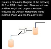
Transcribed Image Text:Create a Kinematic Diagram of the following
RLR or RPR robotic arm. Show coordinate,
and link length and proper orientation
following the Denavit-Hartenberg frame
method. Place you into the above box.
Expert Solution
This question has been solved!
Explore an expertly crafted, step-by-step solution for a thorough understanding of key concepts.
This is a popular solution
Trending nowThis is a popular solution!
Step by stepSolved in 2 steps with 1 images

Knowledge Booster
Learn more about
Need a deep-dive on the concept behind this application? Look no further. Learn more about this topic, mechanical-engineering and related others by exploring similar questions and additional content below.Similar questions
- Create a fourbar linkage design (with moveable pivots at C and D) to move link CD from location C1D1 to C2D2) with COUPLER output. (Show detailed drawing and explain design) (Follow dimensions below)arrow_forwardDetermine a body or system of your own to analyze statically using concept from this class! Requirements: • Draw a static system (either in 2D or 3D). For instance, I may draw a clothes drying rack in 3D. See below for a visual of the clothes drying rack. ● In this drawing prescribe a force or moment at some point on the body. For instance, I may prescribe a force at the top of the drying rack simulating a shirt hanging from the rack. Explain the concepts you would use to figure out an applicable force/moment at another point/member while the body is in equilibrium. For instance, I would use a combination of concepts of FBD/equilibrium and method of joints/sections to find the internal member forces of each drying rack member. 5arrow_forward1arrow_forward
- The link lengths and the values of 02, W2, and y for some inverted fourbar crank- slider linkages are defined in the following table. The general linkage configuration and terminology are shown in the figure. For row a, what is the value of acceleration at point A, if we use the analytical vector loop method? Row Link 1 Link 2 Link 4y 02 W2 a2 6 12 4 9030 10-25 7 19 13 3 16 18 13 18 12 15 la b С d e If 02 002 10 5 14 18 Y 18 O 128.48 in/sec2 O 672.505 in/sec2 O 206.155 in/sec2 O 46.138 in/sec2 03 7585-15-40 4545 24 30 6025-5020 3075-45-5 90150100-65 RB B 04 fter 04 Xarrow_forwardSketch a planar linkage that has the ability to pick up a small ball and move it from one location to another using hinge joint. The sketch of the planar linkage should be able to operate in at least 3 degrees of freedom: rotation along pitch and yaw, and translation through the center of motion.arrow_forwardConsider that we have a 3-R robot as shown in the figure below. The lengths of the links are: 11-12-13=2. The position and posture of the tool's center point is Pt (x₁, y₁, α), the driving variables are 01, 02, 03, and the output variables are v,v,, w.. (It is in the initial position) yo 1₁ Y₁ 0₁ Y₂ 12 02 X1 -X2 V3 13 P₁ X3 a Xoarrow_forward
- Problem 3: The RPH robot of Figure 3 is shown in its zero position. Determine the end- effector zero position configuration M, and the screw axes S; in {s}. n. F -inta. Sorowo- Zs {s} Xs L₁ ŷs Lo 0₁5 L2 02 {b} zb 103 pitch h = 0.1 m/rad Ấb ŷb L3 Figure 3: An RPH open chain shown at its zero position. All arrows along/about the joint axes are drawn in the positive direction (i.e., in the direction of increasing joint value). The pitch of the screw joint is 0.1 m/rad, i.e., it advances linearly by 0.1 m for every radian rotated. The link lengths are Lo = 4, L₁= 3, L2= 2, and L3= 1 (figure not drawn to scale).arrow_forwardPlease assist with this practice question 7. I don't know where to begin with this. Give details on how to do. Thank you.arrow_forward4. A general fourbar linkage configuration and its notation are shown in the following figure and table. Find a 3, a 4,A¼, ABA, AB,Ap for open circuit by vector loop method. Row Link 1 Link 2 Link 3 Link 4 02 Rpa 63 6 2 7 9 30 10 6 30 - 12 - 15 7 3 8 85 25 3 10 6 8 45 -10 10 80 d 7 25 24 - 4 45 e 75 -50 10 300 Rp B A 03 2 X 04 NO O55arrow_forward
arrow_back_ios
SEE MORE QUESTIONS
arrow_forward_ios
Recommended textbooks for you
 Elements Of ElectromagneticsMechanical EngineeringISBN:9780190698614Author:Sadiku, Matthew N. O.Publisher:Oxford University Press
 Mechanics of Materials (10th Edition)Mechanical EngineeringISBN:9780134319650Author:Russell C. HibbelerPublisher:PEARSON
 Thermodynamics: An Engineering ApproachMechanical EngineeringISBN:9781259822674Author:Yunus A. Cengel Dr., Michael A. BolesPublisher:McGraw-Hill Education
 Control Systems EngineeringMechanical EngineeringISBN:9781118170519Author:Norman S. NisePublisher:WILEY
 Mechanics of Materials (MindTap Course List)Mechanical EngineeringISBN:9781337093347Author:Barry J. Goodno, James M. GerePublisher:Cengage Learning
 Engineering Mechanics: StaticsMechanical EngineeringISBN:9781118807330Author:James L. Meriam, L. G. Kraige, J. N. BoltonPublisher:WILEY

Elements Of Electromagnetics
Mechanical Engineering
ISBN:9780190698614
Author:Sadiku, Matthew N. O.
Publisher:Oxford University Press

Mechanics of Materials (10th Edition)
Mechanical Engineering
ISBN:9780134319650
Author:Russell C. Hibbeler
Publisher:PEARSON

Thermodynamics: An Engineering Approach
Mechanical Engineering
ISBN:9781259822674
Author:Yunus A. Cengel Dr., Michael A. Boles
Publisher:McGraw-Hill Education

Control Systems Engineering
Mechanical Engineering
ISBN:9781118170519
Author:Norman S. Nise
Publisher:WILEY

Mechanics of Materials (MindTap Course List)
Mechanical Engineering
ISBN:9781337093347
Author:Barry J. Goodno, James M. Gere
Publisher:Cengage Learning

Engineering Mechanics: Statics
Mechanical Engineering
ISBN:9781118807330
Author:James L. Meriam, L. G. Kraige, J. N. Bolton
Publisher:WILEY