Introductory Circuit Analysis (13th Edition)
13th Edition
ISBN: 9780133923605
Author: Robert L. Boylestad
Publisher: PEARSON
expand_more
expand_more
format_list_bulleted
Question
Solve the ff.
The answer in the solution must be the same in the shown answers.

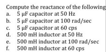
Transcribed Image Text:Compute the reactance of the following
a. 5 µF capacitor at 50 Hz
b. 5 µF capacitor at 100 rad/sec
5 µF capacitor at 60 cps
C.
d.
e.
500 mH inductor at 50 Hz
500 mH inductor at 100 rad/sec
500 mH inductor at 60 cps
f.

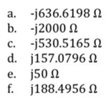
Transcribed Image Text:a.
b.
c.
d.
e.
f.
Ω
- j636.6198
-j2000 Ω
- j530.5165 Ω
j157.0796 Ω
j50 Ω
188.4956 Ω
Expert Solution
This question has been solved!
Explore an expertly crafted, step-by-step solution for a thorough understanding of key concepts.
This is a popular solution
Trending nowThis is a popular solution!
Step by stepSolved in 5 steps with 5 images

Knowledge Booster
Learn more about
Need a deep-dive on the concept behind this application? Look no further. Learn more about this topic, electrical-engineering and related others by exploring similar questions and additional content below.Similar questions
- Two hypothetical circuit element (shown by the blue rectangle), are shown in the figure. We will refer to them as the top circuit and the bottom circuit. Determine the best match to the behavior for each circuitarrow_forwardQuestion S Analyze the following sequential circuit by a) Write down the state equations b) Write down the outpat equations c) Write down the state table for the sequential circuit 4) Draw the state diagram for the sequential circuit &&& Clock Reset. CROarrow_forwardIn a house, a circuit often includes multiple electrical outlets which are parallel-connected to a single voltage source. Each of these circuits also contains a 15-A circuit breaker. Design a parallel-connected circuit which shows three electrical outlets con-nected to a voltage source with a circuit breaker. What is the advantage of having out-lets parallel-connected, and why is a circuit breaker connected in series with the voltage source? Why is the circuit breaker considered a necessary safety item in the circuit?arrow_forward
- The circuit is in continuity mode before the switch is opened. Select one: O a. 2. Select the option that corresponds to the circuit before opening the switch. R₁ O b. 3. O c. 1. E 3. E R₁ E L k E R₁ R₁ 2. R₂ R₂ R₂arrow_forwardA Wheatstone bridge circuit is shown in Figure below, where R1=R:=R=1202, R. represents a resistance-temperature detector (RTD), and voltage source V, = 10 v. Provide the answers to questions 23 – 30. R, R, R,arrow_forwardFIND THE CURRENT, VOLTAGE AND POWER FOR R1,R2,R3,AND R4.arrow_forward
arrow_back_ios
arrow_forward_ios
Recommended textbooks for you
 Introductory Circuit Analysis (13th Edition)Electrical EngineeringISBN:9780133923605Author:Robert L. BoylestadPublisher:PEARSON
 Delmar's Standard Textbook Of ElectricityElectrical EngineeringISBN:9781337900348Author:Stephen L. HermanPublisher:Cengage Learning
 Programmable Logic ControllersElectrical EngineeringISBN:9780073373843Author:Frank D. PetruzellaPublisher:McGraw-Hill Education
 Fundamentals of Electric CircuitsElectrical EngineeringISBN:9780078028229Author:Charles K Alexander, Matthew SadikuPublisher:McGraw-Hill Education
 Electric Circuits. (11th Edition)Electrical EngineeringISBN:9780134746968Author:James W. Nilsson, Susan RiedelPublisher:PEARSON
 Engineering ElectromagneticsElectrical EngineeringISBN:9780078028151Author:Hayt, William H. (william Hart), Jr, BUCK, John A.Publisher:Mcgraw-hill Education,

Introductory Circuit Analysis (13th Edition)
Electrical Engineering
ISBN:9780133923605
Author:Robert L. Boylestad
Publisher:PEARSON

Delmar's Standard Textbook Of Electricity
Electrical Engineering
ISBN:9781337900348
Author:Stephen L. Herman
Publisher:Cengage Learning

Programmable Logic Controllers
Electrical Engineering
ISBN:9780073373843
Author:Frank D. Petruzella
Publisher:McGraw-Hill Education

Fundamentals of Electric Circuits
Electrical Engineering
ISBN:9780078028229
Author:Charles K Alexander, Matthew Sadiku
Publisher:McGraw-Hill Education

Electric Circuits. (11th Edition)
Electrical Engineering
ISBN:9780134746968
Author:James W. Nilsson, Susan Riedel
Publisher:PEARSON

Engineering Electromagnetics
Electrical Engineering
ISBN:9780078028151
Author:Hayt, William H. (william Hart), Jr, BUCK, John A.
Publisher:Mcgraw-hill Education,